
Power saving apparatus for a high-intensity discharge lamp

A technology of high-pressure discharge lamps and power-saving devices, applied in the use of gas discharge lamps, lighting devices, electric light sources, etc., can solve problems such as shortened life, high manufacturing costs, and complicated circuits, so as to reduce power consumption and ensure failure Insurance and Responsiveness Improvement Effects

Inactive Publication Date: 2010-06-09
KAWAMURA ELECTRIC INC +1
View PDF2 Cites 2 Cited by
  • Summary
  • Abstract
  • Description
  • Claims
  • Application Information

AI Technical Summary

Problems solved by technology

[0006] However, since the conventional power saving device 51 always saves the power consumption of the high pressure discharge lamp 54 at a constant power saving rate, if the input voltage fluctuates, the output voltage also fluctuates at the same rate.
Therefore, there is a problem that the illuminance of the discharge lamp 54 becomes unstable, flickering tends to occur, and the service life becomes short.
In particular, if the discharge lamp installed at a high place goes out, it will be difficult to perform maintenance such as replacing the bulb
The conventional devices of Patent Documents 1 and 2 have an inverter and a chopper circuit on the primary side of the transformer, so the lighting state of the lighting load is stable, but because the circuit is complicated, the size is increased, and the manufacturing cost is high, so it is not suitable for a single discharge. The purpose of setting a power saving device in the lamp

Method used


Image

  • Power saving apparatus for a high-intensity discharge lamp
  • Power saving apparatus for a high-intensity discharge lamp
  • Power saving apparatus for a high-intensity discharge lamp

Examples


Embodiment Construction

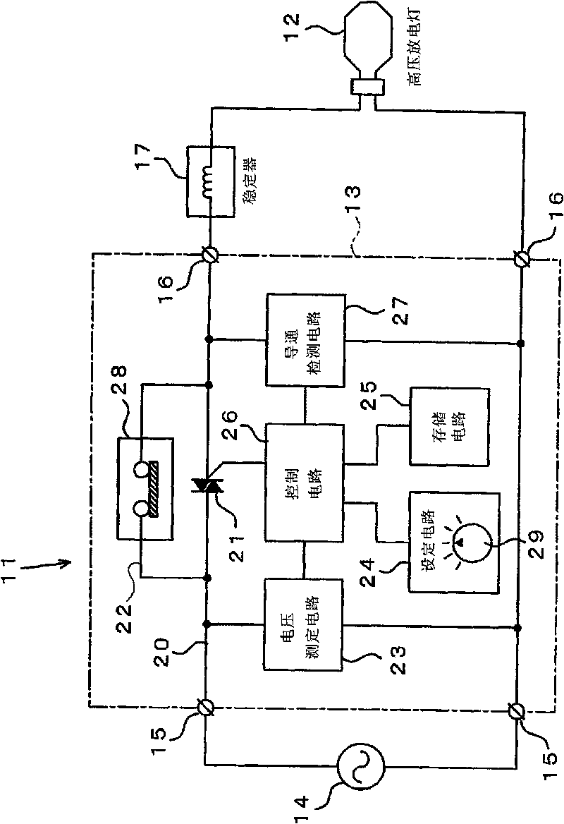
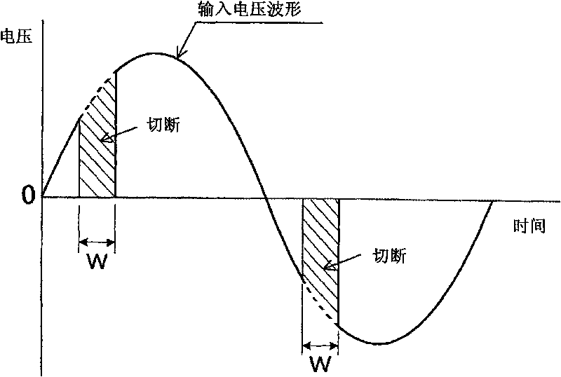
[0019] Embodiments of the present invention will be described below with reference to the drawings. figure 1 is a block diagram functionally showing the configuration of the power saving device, figure 2 It is a flowchart showing the operation of the power saving device. image 3 It is a voltage waveform diagram showing the operation of a TRIAC as a power adjustment element, Figure 4 It is a power characteristic diagram illustrating the result of power saving in the constant output power saving mode.

[0020] (Example)

[0021] Such as figure 1 As shown, the power saving device 11 of this embodiment includes a casing 13 arranged near a high-pressure discharge lamp 12 such as a mercury lamp or a sodium lamp (for example, inside a switchboard). Two input terminals 15 connected to the AC power supply 13 and two output terminals 16 connected to the discharge lamp 12 are arranged on the outer surface of the case 13 . An output terminal 16 is connected to the discharge lamp...


PUM


Abstract

The invention provides a power saving device for high voltage discharging lamps with compact size and low cost, which can perform power saving while keeping the brightness of high voltage discharging lamps such as mercury lamps, sodium lamps or the like. The input voltage from the AC power source is measured by a voltage measurement circuit, the target power outputted to the high voltage discharging lamps is determined by the determination circuit. The waveform processing data is stored in the storage circuit for decreasing the power predicted according to the input voltage to the target power, the control circuit reads waveform processing data from the storage circuit corresponding to the measurement value of the input voltage, for controlling the conduction timing of the TRIAC for powerregulation. A relay is provide on the by-pass circuit by-passing the TRIAC, when the conduction detection circuit detects that the discharging lamp is not conducted, the by-pass circuit is shut down by the relay, power voltage is provided to the discharging lamp in order to prevent turning off of the lamp.

Description

technical field [0001] The present invention relates to a power-saving device for keeping the illuminance constant and reducing power consumption in high-pressure discharge lamps such as mercury lamps and sodium lamps. Background technique [0002] Conventionally, there is known a device for saving power of a high-pressure discharge lamp using a power adjustment element. For example, Figure 5 The power-saving device 51 shown includes: a triac (TRIAC) 53, which is used to cut off the waveform of the voltage input from the AC power supply 52; a setting circuit 55, which is used to set the power-saving rate of the high-pressure discharge lamp ; The power measurement circuit 56 is used for measuring the actual power consumption of the discharge lamp 54; and the control circuit 57 is used for feedback control of the TRIAC 53 so that the measured value satisfies the power saving rate. Such as Figure 6 As shown, the power saving device 51 is configured to always save power cons...

Claims


Application Information

Patent Timeline
IPC IPC(8): H05B41/36
CPCY02B20/202
Inventor 加藤昌幸山内宏夫普拉提普·阿蒙维帝基瓦察
Owner KAWAMURA ELECTRIC INC
Learn More