Apparatus and method for objective perimetry visual field test
An objective and well-equipped technology, applied in the field of visual field test equipment, can solve problems such as aggravated fatigue, difficulty in maintaining gaze, and long test time
Inactive Publication Date: 2010-06-09
UNIVERSITY OF NORTHERN BRITISH COLUMBIA +1
0 Cites 11 Cited by
AI-Extracted Technical Summary
Problems solved by technology
In addition, tests are often lengthy, which also exacerbates fatigue
Difficulty maintaining the gaze due to the fat...
Method used
[0051] The headrest 300 includes a frame 310, a chin rest 320 and a forehead rest 330. Headrest 300 is optional. Using a suitable gaze detection device, the orientation of the subject's gaze can be detected without using a headrest, so as to determine the position of the gaze p...
Abstract
Apparatus for testing a subject's visual field includes a data processor, which can be provided by a general purpose computer, coupled to a pupil tracking system. The data processor is programmed to cause targets to be displayed at different locations on a display screen and to determine from the pupil tracking system whether the subject's pupil has moved in response to display of each target. In some embodiments, the pupil tracking system comprises an infrared camera.
Application Domain
Acquiring/recognising eyesEye diagnostics
Technology Topic
Test objectVisual field loss +10
Image
Examples
- Experimental program(1)
Example Embodiment
[0045] Throughout the following description, specific details are set forth in order that those skilled in the art may provide a thorough understanding of the present invention. . However, to avoid unnecessarily obscuring the disclosure, some well known elements have not been shown or described in detail. Accordingly, the description and drawings are to be regarded as illustrative rather than restrictive.
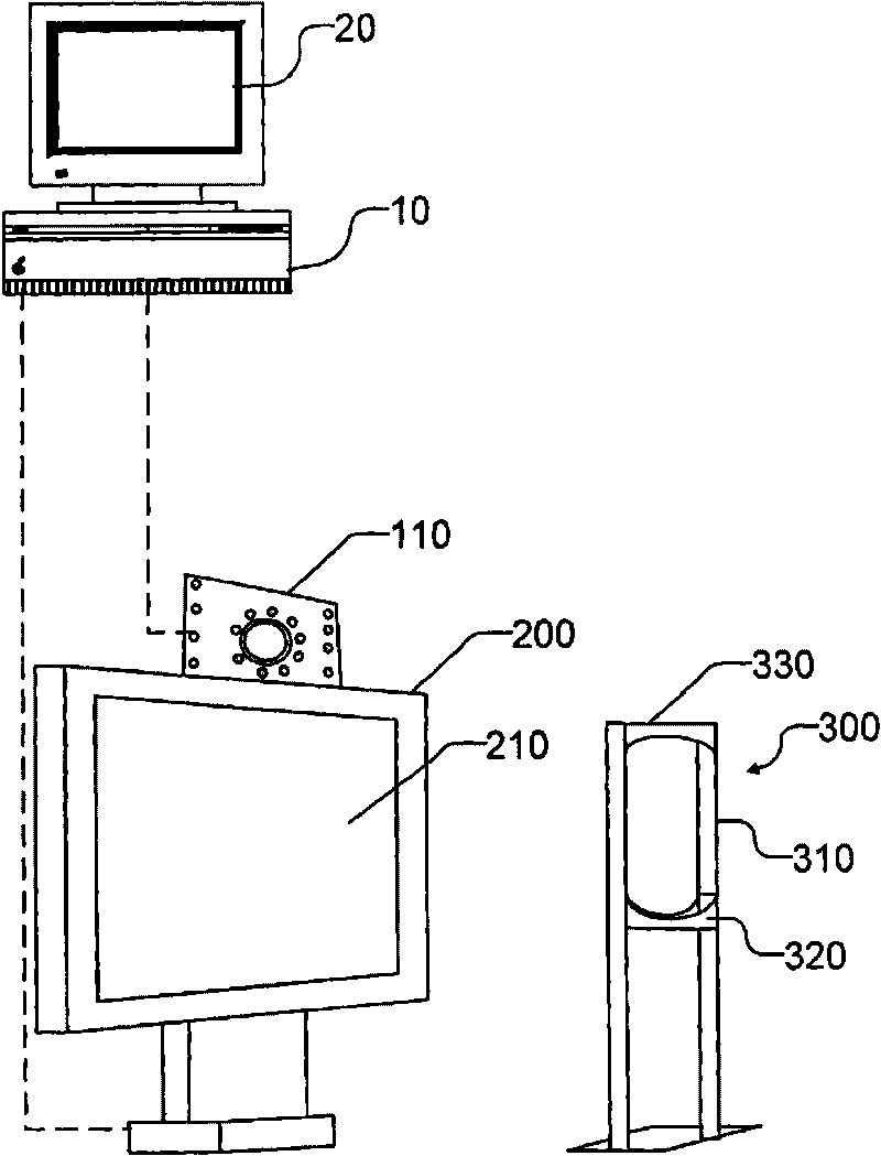
[0046] refer to Figure 1 to Figure 8 , the device 11 according to one embodiment comprises a personal computer 10 . Computer 10 may include components and peripherals typically associated with a personal computer. The computer 10 is connected to and controls a main display 200 and a second optional monitor 20 . The computer 10 is not limited to a personal computer. Computer 10 may include any suitable data processing device, such as an embedded processor, microprocessor, application server, network computer, or similar device.
[0047] In the illustrated embodiment, display 200 comprises a computer monitor. The monitor may have a flat screen. The monitor may include, for example, an LCD display, plasma CRT display, or similar device.
[0048] The gaze detection system 13 is used to determine the orientation of the object's gaze. The gaze detection system may include a suitable pupil tracking system. In the illustrated embodiment, the gaze detection system 13 includes a camera 110 for capturing images of the subject's eyeballs, and based on the image data obtained from the camera 110 , determines the orientation of the subject's gaze. In some embodiments, the image data obtained from the camera 110 is transmitted to the computer 10 and processed on the computer 10 to track where the subject is looking. Alternatively, the gaze detection system 13 may be provided with a dedicated system for processing the image data obtained from the camera 110 .
[0049] In some embodiments, camera 110 includes, for example figure 2 Infrared camera shown. Movement of the subject's pupils is detected by the infrared camera.
[0050]In the illustrated embodiment, device 11 includes a head rest 300 . The headrest 300 is used to keep the subject's head in an ideal position relative to the main display 200 , and can move freely relative to the active infrared camera 110 . The eyes of the subject to be tested may be at any suitable distance from the screen 210 or the main display 200 . For example, the subject's eyes may be approximately 50 cm or so from the screen 210 . When the screen 210 is larger, the distance from the subject's eyes to the screen 210 can be larger, and when the screen is smaller, the subject's eyes should be closer to the screen 210 . A suitable size for the screen 210 may be greater than about 50 cm (measured diagonally).
[0051] The headrest 300 includes a frame 310 , a chin rest 320 and a forehead rest 330 . Headrest 300 is optional. Using a suitable gaze detection device, the orientation of the subject's gaze can be detected without using a headrest, so as to determine the position of the gaze point on the main display 200 . Use of a high-backed chair (not shown) also helps reduce subject head movement.
[0052] The device 11 may be adapted to identify blind spots or blind spots by displaying objects on the display 200 and tracking the resulting eye movements of the objects. In one aspect of the invention, the subject is instructed to look at any object appearing on the primary display 200 with the eye being tested. Under the control of the computer 10 , objects are presented at different positions on the main display 200 . The computer 10 uses the data acquired from the active infrared camera 110 to determine the orientation of the gaze of the eye being tested. After knowing the gaze direction and the position of the eyeball relative to the main display 200 , how to calculate the gaze point on the main display 200 will be further described below.
[0053] When vision is normal, the eyeballs will naturally tend to follow new objects presented on the display 200 . This will reinforce the eyeball's command to move to the new target. When the object presented on the display 200 is located in a severely impaired area of the subject's field of view, no new object will be detected and the eye will not move to the location of the new object. Eye movements or lack of movement in response to the presence of new objects are recorded by computer 10 .
[0054] exist figure 1 In the illustrated embodiment, information related to the operation of the device 11 can be displayed on the second monitor 20 . A second monitor is optional. The device 11 can be configured to display information related to the operation of the device 11 on the primary display 200 at appropriate times. The choice may be based on need for cost, portability, or other reasons.
[0055] For example, the personal computer 10 may be a laptop computer, in which case the second monitor 20 may be built into the computer along with all common components and peripherals such as keyboard, mouse, central processing unit, mass storage device, etc. middle.
[0056] like figure 2 As shown, pupil detection and tracking system 13 includes two illuminators 112 and 114 . For ease of use, the illuminators 112 and 114 may include near-infrared light sources that emit light at wavelengths that are invisible or barely visible to the human eye. For example, lighting elements 114 and 114 may emit light at a wavelength of approximately 875 nm. Camera 110 is capable of sensing the wavelengths emitted by lighting elements 112 and 114 .
[0057] Mounting lighting 112 is used to provide a bright pupil image and mounting lighting 114 is used to provide a dark pupil image. In the illustrated embodiment, this is accomplished by placing the light source of the illumination member 112 near the optical axis 120 of the lens 122 of the camera 110 . The light source of the lighting member 114 is positioned away from the optical axis 120 . exist figure 2 In the illustrated embodiment, illumination elements 112 and 114 each include eight infrared light emitting diodes (LEDs) 116 . The LEDs are arranged on two concentric rings 112A and 114A. The center 118 of the ring is on the camera optical axis 120 .
[0058] In one embodiment, both rings are on the same plane. The inner ring 112 is sufficiently close to the camera optical axis 120 to produce a bright pupil image. The diameter of the outer ring 114A is large enough (the LEDs 116 are positioned away from the camera optical axis 120 to produce a dark pupil image) and bright enough to produce approximately equal illumination as the inner ring 112 . In the illustrated embodiment, the diameter of the inner ring 112A is about the same as the diameter of the lens 122 (15 mm), and the diameter of the outer ring 114A is about 90 mm. These are gained experience points and depend on the characteristics of the camera. In another embodiment, the outer ring 114A is replaced by two parallel lines 114B of LEDs 116 that are separated from the figure 1 The shown camera lens 122 is approximately 75 mm. The first and second lighting elements 112 and 114 may include other arrangements of light sources.
[0059] The gaze tracking system controls the illuminators 112 and 114 such that the camera 110 can capture images of some subjects' eyes under the illumination of the illumination 112 and other subjects' eyes under the illumination of the illumination 114 . For example, the turning on and off of lights 112 and 114 may be synchronized with the operation of camera 110 such that the camera captures even and odd frames illuminated by lights 112 and 114, respectively. For example, when the LEDs of the inner ring 112A are on, even-numbered frame images are captured, while when the LEDs of the outer ring 114 are on, odd-numbered frame images are captured.
[0060] Several pupil localization techniques have been published and are well known to those skilled in the art. Any technique suitable for pupil localization or other techniques for judging the gaze direction of an object can be applied to the embodiments of the present invention. A basic embodiment of an algorithm for locating a subject's pupil in an image acquired from the camera 110 is as follows. Define the following parameters:
[0061] ●F e is the data of the even frame, F o For data of odd frames, both even and odd frames are expressed in grayscale, or can be converted to grayscale.
[0062] ●E i,j is the pixel in column i and row j in an even frame, O i,j is the pixel in column i and row j in an odd frame.
[0063] ●F d is the difference between two frames.
[0064] f d Calculated as follows:
[0065] D. ij =ABS(E ij -O ij ) (1)
[0066] Here, D i,j for F d The pixel in column i and row j of .
[0067] Calculate F d The sum of the pixel values of each i-th column in . Define colMax to be the maximum of these sums. Calculate F d The sum of the pixel values of each row j in . Define rowMax to be the maximum of these sums. The center of the pupil is at (rowMax, colMax). Other suitable algorithms may also be used.
[0068] There are three different coordinate spaces relevant to pupil tracking and eye testing: camera coordinates, screen coordinates, and eye coordinates. The camera coordinates are used to identify the location of the subject's pupil in the image acquired from the camera 110 . For example, the aforementioned algorithm may be used to determine the camera coordinates of the subject's eyeball.
[0069] The screen coordinates are used to identify where on the main display 200 the subject's eyeballs are looking. The screen coordinates can be determined by the specific position of the pupil from the camera coordinates of the camera 110 and a transformation function.
[0070] The eyeball coordinates are used to distinguish the area of the eyeball of the object viewing the current target 620 (such as Figure 5 shown). like Image 6 As shown, the eye coordinates can be determined from the position of the subject's current gaze (typically the position of the previous target 610 seen by the subject) and the relative screen coordinates of the current target 620 .
[0071] Assuming that the object is located directly in front of the camera 110 and the main display 200 is rectangular, the trapezoid t in camera coordinates corresponds to the area of the main display 200 in screen coordinates. The transformation function of the corresponding relationship between the camera coordinates and the screen coordinates can be established by determining the corresponding camera coordinates of three nonlinear points whose screen coordinates are known. In one embodiment, the pupil position in camera coordinates is established at each of the four corners of the main display 200, while a mathematical function is generated that establishes the mapping between the rectangle representing screen coordinates and the resulting trapezoid in camera coordinates .
[0072] exist image 3 Shown in is the screen 210 of the main display 200, w and h are the pixel values of the width and height of the screen 210, respectively. define(x s ,y s ) is the point 710 on the primary display 200 that the pupil is currently looking at.
[0073] Figure 4 details a trapezoid t with an upper base y 1 and bottom edge y 2 , and the x coordinates are x 1 , x 2 , x 3 , x 4 The upper left vertex, the upper right vertex, the lower left vertex and the lower right vertex. (x c ,y c ) is the position of the pupil in camera coordinates, (x s ,y s ) on the main display 200 where the eyeball is looking at 710 (gaze point 710 on the display 200).
[0074] In order to find out (x c ,y c ) and (x s ,y s ), define d(x, y) as the distance from the point (x, y) to the left side of the trapezoid, and w(y) as the width of the trapezoid in the y-axis direction. Can be expressed as follows:
[0075] d ( x , y ) = x - x 1 + y - y 1 y 2 - y 1 ( x 3 - x 1 ) - - - ( 2 )
[0076] w ( y ) = x 2 - x 1 + y - y 1 y 2 - y 1 ( x 3 + x 4 - ( x 1 + x 2 ) ) - - - ( 3 )
[0077] x s = d ( x c , y c ) w ( y c ) w - - - ( 4 )
[0078] y s = ( y c - y 1 ) h ( y 1 - y 2 ) - - - ( 5 )
[0079] Equations (4) and (5) can be used to determine the screen coordinates corresponding to the camera coordinates of the subject's pupil.
[0080] eye coordinates
[0081] like Image 6 as shown, Figure 5 The eye region that sees the current object 620 shown in can be determined based on the corresponding positions of the previous object 610 and the current object 620 (assuming the subject is still looking at the previous object 610). Shown in 5 is a grid representing the retina (eyeball coordinates). Image 6 Shown is a grid (screen coordinates) representing the main monitor.
[0082] screen to eyeball
[0083] Make the previous target 610 in the center of the eye grid ( Figure 5 ). The relative distance from the previous target 610 to the current target 620 is in Figure 5 Retina grid shown and Image 6 The screen grids shown are all equal.
[0084] eyeball to screen
[0085]The relative distance of the center of the eyeball grid is equal to the relative distance of the previous target 610 and the new target 620 .
[0086] Pupil Motion Matching
[0087] like Figure 7 As shown, the eye movement of the subject determined by the gaze detection system 13 can be used to determine whether the subject perceives the current target 620 at a given location on the main display 200 . This can be done by comparing the current position 720 of the eye relative to its position 710 when the previous target was present with the relative distance between the current target 620 and the previous target 610 on the display 200 .
[0088] Figure 7 Shown is how θ and d, which represent the relative positions of the two eyeball positions 710 and 720, are obtained. θ and d can be obtained in the same way as calculating the relative positions of the two targets 610 and 620 . The two sets of θ and d thus obtained can then be compared to see if they are within the allowable margin of error. If so, it is likely that the subject did perceive the new object 620 at the corresponding eye grid location 720 . If the subject does not change the direction of gaze to the location of the new target within the allowed time (eg, about 1 to 2 seconds), the subject may be deemed not to have seen the new target.
[0089] target generator
[0090] The device 11 includes a target generator that generates the position of the target displayed on the screen 210 to test the field of view of the subject. The object generator may include, for example, computer software instructions executing on computer 10 . The object generator starts at the eye mesh ( Figure 7 ) to select target locations for under-tested regions. The target generator checks if the target position corresponds to a position on the screen 210 (i.e. a position within the screen grid - Image 6 ). If not, the target generator will choose another target location. Alternatively, the target generator generates target positions that always correspond to positions on the screen grid.
[0091] If none of the undertested areas of the subject's field of view can correspond to a location on the screen 210 , the object generator can select a location that has been adequately tested but can correspond to a location on the screen 210 . For example, the goal generator may set the position of the next goal on a straight line between the previous goal 610 and the goal displayed immediately before the goal 610 . For example, the next goal may be set at the midpoint of the line segment between the previous goal 610 and the goal displayed just before goal 610 .
[0092] New targets can be displayed at suitable intervals, eg every few seconds, eg every 1 or 2 seconds, etc., until the test is complete. The new target can be displayed after the subject has seen the previous target (judged by the subject's gaze direction moving to the previous target), or the subject cannot see the previous target (by the subject's gaze direction not moving to the previous target within a threshold period of time). a target). The time between displaying consecutive targets may vary slightly, eg may be displayed randomly.
[0093] Targets can be circular. For example, the target may be a circular ring displayed onto the screen 210 of the main display 200 . This is not mandatory. In some embodiments, objects may include other shapes or images, such as small icons or pictures. For example, an icon or picture could be a group of lively children trying to see new objects as they appear. The objects may be suitably colored to distinguish them from the background displayed on the screen 210 . For example, the target can be white or red, while the background can be black. However, these are not mandatory. In some embodiments, the contrast between the object and the background can be adjusted by an operator or automatically. Each display target may include a plurality of pixels on the main display 200 that can display different effects from the background of the display 200 at runtime.
[0094] Testing continues until a sufficient number of objects are displayed to adequately test the field of view of the subject being tested. In some embodiments, the subject's field of view is divided into regions, and testing continues until at least two objects have been displayed at positions corresponding to each region of the field of view. Continue testing until the results for each area are confirmed. For example, in some embodiments, an area is considered sufficiently tested if both targets, objects, within the area can be successfully seen or cannot be seen. If an object within an area successfully sees only one object but not a second, the result is considered indeterminate and more objects need to be displayed in the corresponding location of the area. In order to save the time of a test, the target display times in an area can be limited to a reasonable value. For example, in some embodiments, each region is tested no more than three times.
[0095] The field of view can be divided into any reasonable number of regions. These regions can be, but are not limited to, equal in size. In some embodiments, the field of view is divided into 9 to about 150 regions. For example, the field of view can be divided into an array of regions with dimensions 3x3, 7x7, 12x12, etc.
[0096] Medical scotomas tend to affect a considerable area of vision, so in many applications it is not necessary to test at too high a resolution. For example, an important diagnosis can be made on the basis of dividing the field of view of one eye into a 4×4 grid, ie, the field of view is divided into only 16 parts. If you divide the field of view more finely into, say, a 5x5 grid (25 tiles), a 5x4 grid (20 tiles), a 5x6 grid (30 tiles), or even a 6x6 grid (36 small blocks), more effective data can be obtained.
[0097] Scotomas (blind spots) with varying degrees of damage to the light path usually begin in different areas of the visual field. Glaucoma first appears around the common blind spot in the central area, where the optic nerve exits the eye and is therefore not the light-receiving area. However, brain damage along the optic nerve tends to affect more extensively and not be limited to a central location. Therefore target generators can be set to focus on multiple areas. In some embodiments, the user of device 11 may designate specific areas of the field of view to focus testing on. In some embodiments, the target generator may focus on or focus exclusively on these areas.
[0098] In some embodiments, the target on screen 210 is initially displayed as a small dot, which then dynamically expands until a response occurs. For example, the target may first be displayed as a ring with a smaller diameter, for example 0.5 cm. The direction and speed of its expansion can be controlled. While the initial target is within the true dark spot, the expanding target will eventually break through the dark spot's boundaries and elicit a response. An optimized test can be performed to determine the complete exact area of the subject's field of view.
[0099] optimization test
[0100] In some embodiments, optimized testing may be performed. There are many ways to optimize. For example, if a subject cannot see an object at a particular location on the eye grid, the object generator will still test at a slightly different location within the same area to see if the object can be seen at that different location. In an alternative embodiment, if a subject cannot see a target at a certain location on the eye grid, an additional target that is slightly larger and/or brighter than the previous target will be displayed at or near that location. This step can be repeated until the target is large enough for the subject to observe the target. It is not necessary to expand the target uniformly. The computer program can be tuned so that the target preferentially expands towards areas of the field of view that need more data.
[0101] In some embodiments, the computer 10 is programmed to screen all or a selected portion of the subject's field of view by displaying objects at locations scattered around the field of view being measured. Subsequently, enlarged targets can be provided during the screening process to areas where the target is not visible to the subject.
[0102] In some embodiments, device 11 includes an expansion element for expanding the field of view that can be tested using display 200 . These elements may include fixed light sources 17, other fixed objects (not shown) other than the display 200, an additional display 201 capable of displaying objects, and the like. These expansion elements can be controlled by the computer 10 .
[0103] Many conditions, such as glaucoma, typically manifest as visual loss in the peripheral portion of the visual field. Many conditions, such as macular degeneration and many neurological conditions, show visual decline in the more central parts of the visual field. To help diagnose this latter condition, it may be necessary to test only the central portion of the visual field. It may only require a test center 15°, 20°, 25°, 30°, 40°, 50°, 60° or 70° to help diagnose a particular condition. In other cases, however, the entire field of view needs to be tested. Device 11 may be configured to test only selected portions of the field of view.
[0104] Figure 8 A flowchart of an example method for testing visual field of the eye. Figure 8 Also shown are the steps performed by the software running on the computer 10 and given instructions to the subject. In some embodiments, instructions may be given to the subject by displaying the instructions on the primary display 200, as well as in speech synthesizers, pre-recorded audio instructions, and the like.
[0105] In step 801, the device 11 is initialized and the hardware system is assembled. The subject is instructed to place his/her chin in the proper position (eg, on the chin rest 310). Test only one eye at a time by instructing the subject to close one eye, or use a physical device such as an eye patch to block the view of the other eye.
[0106] In step 802, the targets are sequentially displayed on the screen 210 in sufficient locations to be calibrated. Targets are displayed on each corner of the screen 210, for example. Instruct the subject to move their eyes to view the target displayed on the screen.
[0107] In step 803, record the position of the eyeball when watching the display object in step 802. Here, the target is located on the four corners of the screen 210, and the parameter x in equations (2) to (5) can be obtained 1 , x 2 ,y 1 ,y 2.
[0108] In step 804, the parameter x obtained from step 803 is used 1 , x 2 ,y 1 ,y 2 to establish equations (2) to (5).
[0109] In step 805, at the specified position (x' s2 ,y' s2 ) to display the target, which is located at the center of the screen 210 or other positions, and set it as the target t2. The subject is required to look at target t2, although the eye is naturally drawn to the target, this requirement is not required. The system then finds the position of the eyeball on the camera 110, and uses this position to find the corresponding position on the display (x s2 ,y s2 ). Then compare it with the target t2(x' s2 ,y' s2 ) to determine whether the object's eyeballs are looking at the target t2. The above steps are repeated until it is determined that the eyeballs of the subject are looking at the target t2.
[0110] In step 806, set t1 equal to t2, and thus set (x s1 ,y s1 ) is equivalent to (x s2 ,y s2 ), (x' s1 ,y' s1 ) is equivalent to (x' s2 ,y' s2 ). Now the original t2 is the fixed target t1. When the subject's eyeball looks at t1, it can be judged whether the eyeball responds to the new target t2 appearing somewhere on the screen, so as to test a certain position of the subject's field of vision.
[0111] In step 807, a new target t2(x' s2 ,y' s2) to test whether the subject will pay attention to the new target.
[0112] In step 808 , the new target t2 is displayed on the screen 210 .
[0113] In step 809, wait for a predetermined long time, and continuously test whether the eyeball moves towards the new target t2 during this time. Note that steps 809 and 810 are partially performed simultaneously.
[0114] In step 810, monitor the position (x c , c y ), and calculate the position of the eye on the display 210 (x' s2 ,y' s2 ). Position t1(x' on screen 210 s1 ,y' s1 ) and t2(x’ s2 ,y' s2 )A known. calculate(x' s2 ,y' s2 ) and (x s2 ,y s2 ), and judge whether the eyeball has looked at t2 again within a predetermined error range.
[0115] In step 811, if the eyeball does not move to t2 within the predetermined time, the system records it as a failure point, and this point in the visual field is also recorded as a potential blind spot.
[0116] In step 812, if the eyeball has moved to position t2 within a predetermined margin of error, it is assumed that the eye has observed the object at position t2, and this point in the field of view is also recorded as potentially visually functional.
[0117] Multiple inspections of both potential blind spots and areas of possible visual function in the field of view are preferably performed to reduce random errors.
[0118] In some embodiments described herein, computer 10 may display, store, or further process data representing visual field test results. For example, computer 10 may draw a picture to show where the subject's eyes are sensitive and insensitive, create a table or other data structure to show the success rate for each area of the subject's eye, or the like.
[0119] The foregoing embodiments reduce and generally eliminate the need for any verbal response or physical response to be provided by the subject to indicate whether the target is visible or invisible. Subjects are only required to follow simple instructions: "When you see a new object appear on the screen, look at the new object", and even these are unnecessary, as the eyes will naturally be caught in the field of vision suddenly Attracted by new goals.
[0120] Some embodiments can be used to test the field of vision of non-verbal subjects, these subjects may not indicate a response with agile manual manipulation of buttons, but when the subject is correctly indicated and does not change gaze until a new target appears, the change of gaze has already occurred. Indicates the response. Unlike center-fixed designs, this reduces subject boredom after prolonged periods of tedious and lengthy testing with a single target.
[0121] Furthermore, in order to enhance the objectivity of the visual field test, different embodiments of the present invention can reduce the time for performing the visual field test. Certain embodiments may also greatly reduce the cost of equipment used to perform visual field testing. Some embodiments are particularly useful in providing information for the diagnosis of neurological problems.
[0122] While the embodiments described here were tested directly in front of the screen, there is no reason why this must be the case. The same hardware, algorithms and ideas can be used for various applications. For example, the normal range of vision can reach nearly 200° in the horizontal direction of the front of the eye. Test whether a subject sees an object on the display by directing the subject's gaze to certain points off the display, which allows the entire area of the field of view to be tested, not limited to the limited area shown by the display.
[0123] It will be apparent to those skilled in the art to use the device with other standard, or non-standard visual field tests. Various changes may be made without departing from the inventive concept, and the "expanded target" test may also be performed by at least some other means of measuring the field of view.
[0124] In some embodiments, the device includes a data processor that executes software instructions that cause visual field testing in the general method described herein. Software instructions may be stored in a data processor readable memory. Aspects of the invention may be provided in the form of a software product. The software product may comprise any medium carrying a set of computer readable instructions executed by a data processor to implement the method of the present invention. A software product according to the present invention may comprise, for example, physical media such as magnetic data storage media (including floppy disks and hard drives), optical data storage media (including CDs and DVDs), electronic data storage media (including optical disks, flash memory, memory) or similar product. The computer readable instructions on the software product may be compressed or encrypted.
[0125] The components mentioned above (such as software modules, processors, accessories, devices and circuits, etc.), unless otherwise specified, the components referred to (including the "method") should be understood as including Equivalents are any components capable of performing the function of the recited components (ie, functionally equivalent), including components that perform the functions disclosed in the illustrated embodiments of the invention but are not structurally the same.
[0126] While a large number of example aspects and embodiments are discussed above, those skilled in the art will appreciate that certain modifications, permutations, additions and combinations of subsets thereof are possible. Accordingly, the appended claims presented hereinafter should be understood to embrace all such modifications, permutations, additions and subset combinations within their true spirit and scope.
PUM


Description & Claims & Application Information
We can also present the details of the Description, Claims and Application information to help users get a comprehensive understanding of the technical details of the patent, such as background art, summary of invention, brief description of drawings, description of embodiments, and other original content. On the other hand, users can also determine the specific scope of protection of the technology through the list of claims; as well as understand the changes in the life cycle of the technology with the presentation of the patent timeline. Login to view more.