Production technology for blanking by using a through-hole type universal joint finish forging pot shell capable of moving axially

A technology of axial movement and production process, which is applied in the direction of manufacturing tools, forging/pressing/hammering machinery, couplings, etc., and can solve the problem of a large proportion of surplus materials

Active Publication Date: 2010-06-16
江苏威鹰机械有限公司
View PDF2 Cites 14 Cited by
  • Summary
  • Abstract
  • Description
  • Claims
  • Application Information

AI Technical Summary

Problems solved by technology

[0005] The invention provides an axially movable through-hole type universal joint precision forging groove shell blank production process, which main...

Method used


Image

  • Production technology for blanking by using a through-hole type universal joint finish forging pot shell capable of moving axially
  • Production technology for blanking by using a through-hole type universal joint finish forging pot shell capable of moving axially
  • Production technology for blanking by using a through-hole type universal joint finish forging pot shell capable of moving axially

Examples


Embodiment 1

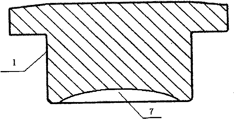
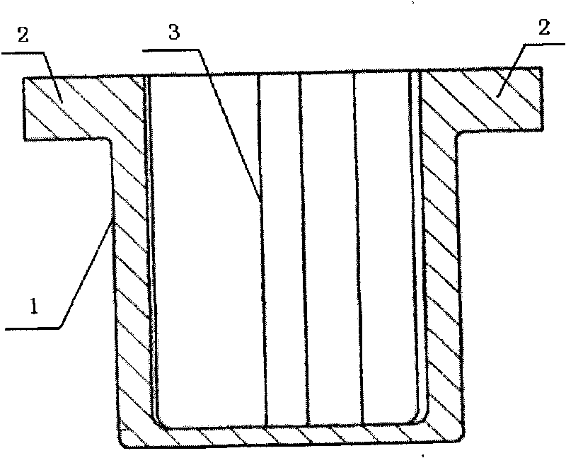
[0016] Embodiment 1: see attached figure 1 with attached figure 2 , a production process for axially movable through-hole universal joint precision forging groove shell blanking, including blanking, heating, and after the metal material is heated after blanking, it is partially upset and extruded in the billet mold , upsetting in a closed cavity to form a rod part 1 and a blank disk part, the rod part 1 is a cylindrical structure, one end is connected with the blank disk part, and the other end is a concave structure, and the concave surface structure The inner cavity 7 is a circular arc surface structure, and the difference between the product of the diameter of the rod part 1 and the maximum length of the rod part 1 and the volume of the rod part is not less than the volume of the inner hole formed by the reverse extrusion of the flange part, and then the preset The formed billet is put into the cavity of the final forging die, and the upsetting billet is back-extruded on ...

Embodiment 2

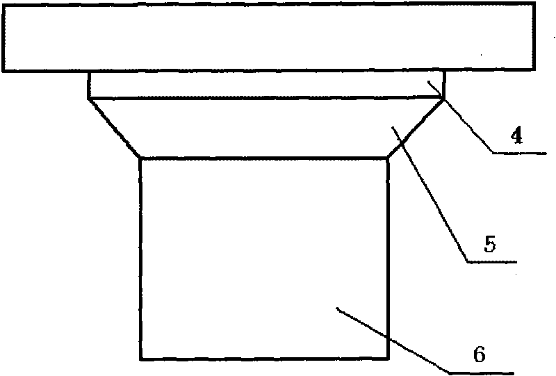
[0017] Embodiment 2: see attached image 3 with attached figure 2 , a production process for axially movable through-hole universal joint precision forging groove shell blanking, including blanking, heating, and after the metal material is heated after blanking, it is partially upset and extruded in the billet mold , upsetting in a closed cavity to form a rod part 1 and a blank disk part, the rod part 1 is divided into three connected sections, the first section 4 and the third section 6 are cylindrical structures with different diameters, the second section The second section 5 is the transition section between the first section and the third section. The transition section 5 is a solid part formed by a circle whose diameter gradually decreases. The difference between the product of the total length and the volume of the rod part 1 is not less than the volume of the inner hole formed by the reverse extrusion of the flange part; Reverse extrusion, the center of the billet f...


PUM


Abstract

The invention discloses a production technology for blanking by using a through-hole type universal joint forging pot shell capable of moving axially. The production technology comprises the following steps: blanking, heating, performing local upsetting and extruding in a blanking impression to form a pole part and a blank disk part, wherein the pole part is composed of cylindrical entity parts with different diameters and transition parts thereof, each transition part is an entity part formed by rounds with gradually increased diameter or gradually decreased diameter, and the difference between the product of the maximum diameter of the pole part and the overall length of the pole part and the volume of the pole part is less than the volume of the inner hole which is formed through the backward extrusion of a flange part; then placing the blank in a finishing impression, performing backward extrusion on the blank disk part to form an inner hole ball path in the centre of the blank, perform extrusion molding on the blank disk part to form the flange part of the product, sawing the bottom and dressing. The invention mainly solves the technical problem that the proportion of technical excess material is larger in the existing forging technology, saves raw materials and reduces the production cost.

Description

technical field [0001] The invention relates to a production process of a through-hole type universal joint precision forging groove shell which can move axially, in particular to a method of making a preformed blank by upsetting according to the metal flow forming rule, and then making it into a preformed blank in the final The production process of forging billet products in the mold cavity. Background technique [0002] Due to its complex structure and difficult processing and testing, the axially movable universal joint has many excellent properties such as compact structure, light weight, low noise, high reliability, and maintenance-free. At present, most of the transmission systems of cars in the world use the universal joint as a key transmission component. The inner cavity of this product is evenly distributed in the inner hole by the arc surface, and the ball lane is naturally formed in the inner hole. It needs to be high. At present, manufacturers at home and abr...

Claims


Application Information

Patent Timeline
IPC IPC(8): B21J5/06B21J13/02F16D3/16
Inventor 张太良万永福
Owner 江苏威鹰机械有限公司
Why Eureka
Try Eureka