Braking mechanism of rotary drawing and blowing machine

A braking mechanism and stretch blowing machine technology, which is applied in the field of braking mechanisms and plastic hollow container stretch blow molding machines, can solve the problems that the rotating spindle cannot be reliably stopped, the cylinder and the rotating spindle are easily damaged, and the brake pads are easy to fail. Achieve the effect of avoiding damage to the rotating spindle, low maintenance rate, and good braking effect

Inactive Publication Date: 2010-06-16
浙江东方州强塑模实业有限公司
View PDF0 Cites 7 Cited by
  • Summary
  • Abstract
  • Description
  • Claims
  • Application Information

AI Technical Summary

Problems solved by technology

The rotating spindle is generally driven by a motor, but when the motor stops, due to the inertial force, the rotating spindle cannot stop reliably and stably, so a braking mechanism is generally provided, and the existing braking mechanism is fixed on the rotating spindle For the brake disc, two opposite cylinders are used, and the piston rods of the two cylinders are respectively fixed to the brake pads. When braking is required, the piston rods of the two cylinders are stretched

Method used


Image

  • Braking mechanism of rotary drawing and blowing machine
  • Braking mechanism of rotary drawing and blowing machine

Examples


Embodiment Construction

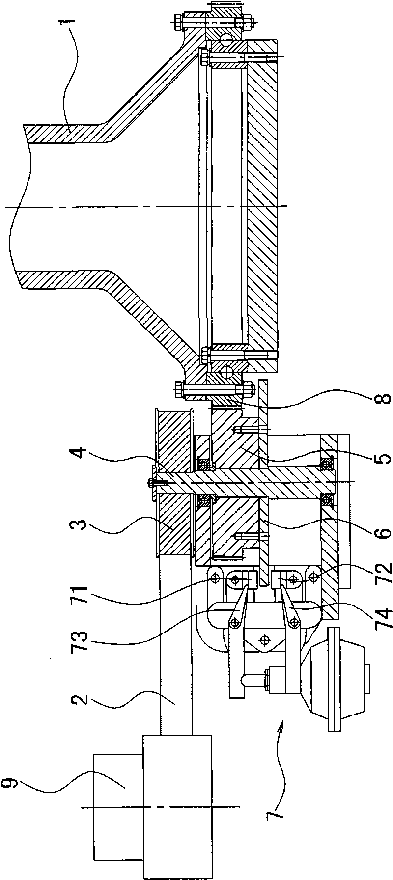
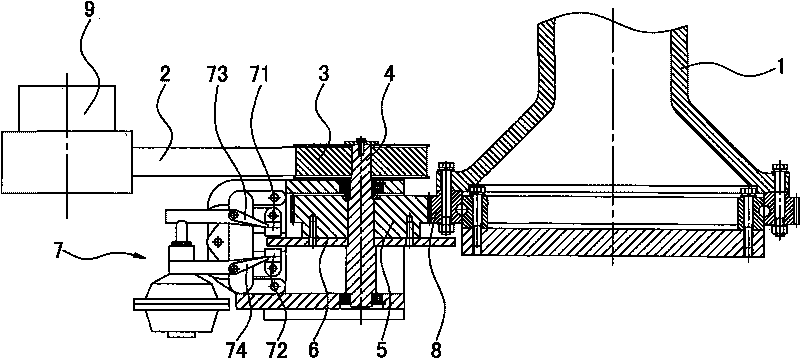
[0008] The invention discloses a braking mechanism of a rotary stretch-blow machine. The rotary stretch-blow machine includes a feeding mechanism, a heating device, a stretch-blow mechanism and a bottle fetching mechanism. The stretch-blow mechanism includes a stretch mechanism, a blow mechanism and an opening mechanism. The mold clamping mechanism and the stretching and blowing mechanism are driven by the rotating spindle to rotate in the circumferential direction, and the rotating spindle is driven by the motor, such as figure 1 As shown, it is characterized in that a driven gear 8 is installed on the bottom of the rotating main shaft 1, and the motor 9 is connected to the transmission shaft 4 through the synchronous belt 2 and the synchronous pulley 3, and the transmission shaft 4 is externally fixed to the driving gear 5, and the driving gear 5 is meshed with the driven gear 8, the driving gear 5 is fixedly connected to the brake disc 6, and the top surface and the bottom s...


PUM


Abstract

The invention relates to a braking mechanism of a rotary drawing and blowing machine. The rotary drawing and blowing machine comprises a feeding mechanism, a heating device, a drawing and blowing mechanism and a bottle taking mechanism, wherein the drawing and blowing mechanism comprises a drawing mechanism, a blowing mechanism and a mold opening and closing mechanism. The drawing and blowing mechanism is driven by a rotary main shaft to rotate in a circumferential direction, and the rotary main shaft is driven by a motor. The braking mechanism is characterized in that the lower part of the rotary main shaft is provided with a driven gear; the motor is connected with a transmission shaft through a synchronous belt and a synchronous pulley, and a driving gear is fixedly connected outside the transmission shaft; the driving gear is mutually engaged with the driven gear, and a braking disc is fixed connected under the driving gear; and the top and the bottom surfaces of the braking disc are respectively in contact with an upper brake pad and a lower brake pad of a brake. The technical scheme has the advantages that the braking disc is installed on the additional transmission shaft, the transmission shaft transmits power to the rotary main shaft through the gears, which avoids damaging the rotary main shaft, and thus, the maintenance rate is low and the cost is reduced; and the special brake is used for control, so that service life is long and the braking effect is good.

Description

technical field [0001] The invention relates to a plastic hollow container stretch-blow molding machine, in particular to a braking mechanism of a rotary stretch-blow machine, and belongs to the field of plastic machinery manufacturing. Background technique [0002] Hollow plastic containers such as mineral water bottles and oil bottles are processed by injection stretch blowing. First, plastic raw materials (such as PET, etc.) are injected into bottle tubes by an injection molding machine, and then the bottle tubes are heated by a heater, and then heated by a stretch blowing machine. The final bottle tube is stretch-blow-molded. Due to the low working efficiency of the reciprocating stretch-blow machine, someone invented the rotary stretch-blow machine. The rotary stretch-blow machine has a rotating main shaft. On the radial direction of the rotating main shaft, a plurality of stretching mechanisms, blowing mechanisms and The stretch blowing mechanism composed of mold open...

Claims


Application Information

Patent Timeline
IPC IPC(8): B29C49/42B29C49/28
Inventor 王自强
Owner 浙江东方州强塑模实业有限公司
Why Eureka
Try Eureka