
Vehicle oil pan assembly

An oil pan and assembly technology, which is applied in the installation/connection of engine components, machines/engines, and lubricant purification devices, etc., can solve problems such as difficulty in ensuring cleanliness, inconvenient cleaning and disassembly, and affecting production takt time. , to achieve the effect of shortening production cycle, ensuring cleanliness and reducing vaporization

Inactive Publication Date: 2010-06-16
CHERY AUTOMOBILE CO LTD
View PDF0 Cites 6 Cited by
  • Summary
  • Abstract
  • Description
  • Claims
  • Application Information

AI Technical Summary

Problems solved by technology

Using the form of 3 above, the assembly is more complicated when the engine is short-haired. It is necessary to assemble the separator and then assemble the oil collector, and then install the oil pan, which affects the production cycle.
With the above-mentioned structural forms of 4 and 5, after the oil collector is integrated with other components, it is inconvenient to clean and disassemble, and it is difficult to ensure the cleanliness

Method used


Image

  • Vehicle oil pan assembly
  • Vehicle oil pan assembly
  • Vehicle oil pan assembly

Examples


Embodiment Construction

[0028] The present invention will be described in detail below in conjunction with the accompanying drawings.

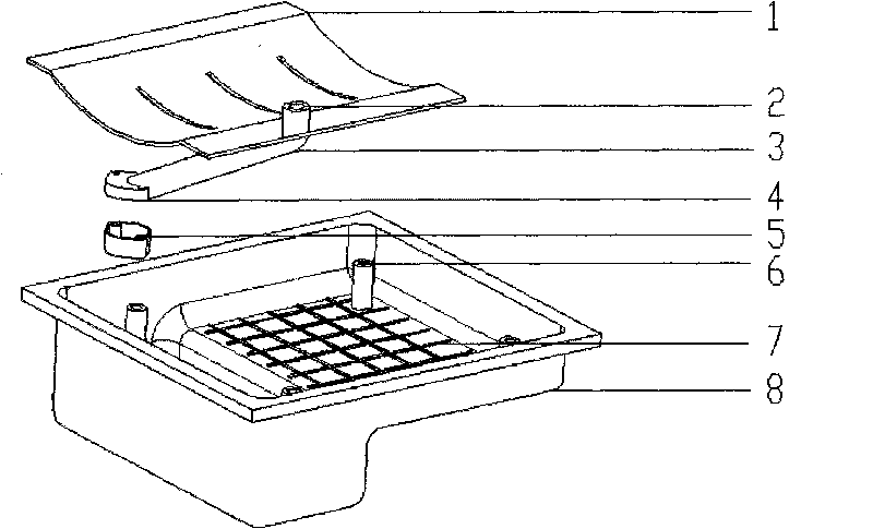
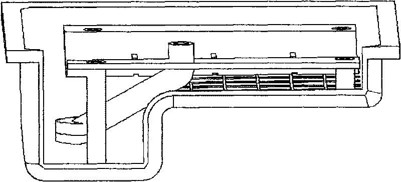
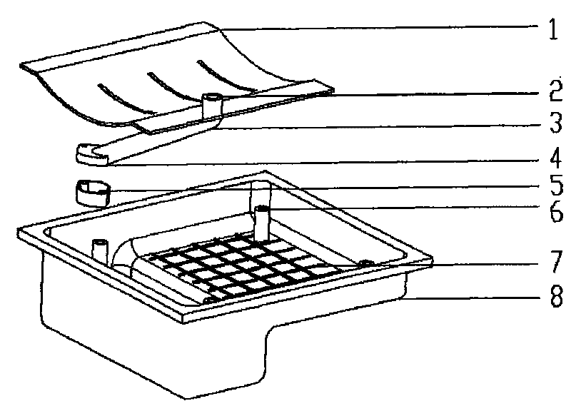
[0029] Such as figure 1 As shown, the oil pan assembly of the present invention includes an oil pan 8, a separator 1 and an oil collector, wherein the oil collector consists of an oil suction pipe 3, an upper part 4 of an oil suction pan and a lower half of an oil suction pan with a strainer 5 composition. Oil pan 8, dividing plate 1 and engine oil collector are all plastic parts. Wherein the oil suction pipe 3 of the oil collector and the upper part 4 of the oil suction pan are made into a non-detachable part with the partition plate 1 by means of hot plate welding. The lower part 4 of the oil suction pan with the strainer is installed together with the upper part 4 of the oil suction pan through bolts to form a complete oil collector. The entire partition 1 is connected together by bolts and the support columns 6 on the oil pan. The oil outlet 2 of the oil coll...


PUM


Abstract

The invention discloses an oil pan assembly which comprises an oil pan, a diaphragm and an engine oil collector, wherein the engine oil collector consists of an oil suction pipe, the upper half part of an oil suction disc and the lower upper half part of the oil suction disc, which is provided with a filter screen, and the oil pan, the diaphragm and the engine oil collector are all plastic parts; and the oil suction pipe and the upper half part of the oil suction disc of the engine oil collector form an unable-dismantled part with the diaphragm through a mode of hot plate welding, and the lower upper half part of the oil suction disc, which is provided with the filter screen, and the upper half part of the oil suction disc are installed together through bolts so as to form the complete engine oil collector. In the invention, the oil pan, the diaphragm and the engine oil collector are integrated into a whole, and an engine can be directly assembled when being assembled, thereby shortening the production beat; in addition, the oil bottom shell, the diaphragm and the engine oil collector are all the plastic parts, thereby having light quality and greatly reducing the quality of the engine; and the part with the filter screen on the engine oil collector can be dismantled, thereby enabling the engine oil collector to be convenient to dismantle and clean.

Description

technical field [0001] The invention belongs to the field of automobile engines, in particular to an oil pan assembly of an automobile engine. Background technique [0002] At present, the structural forms of the oil pan mainly include the following types: [0003] 1. The oil pan is a stamped part, and the separator is also stamped and welded inside the oil pan. The oil pan and the separator cannot be disassembled. [0004] 2. The oil pan is cast aluminum, and the separator is assembled in the oil pan through the ribs at the bottom of the oil pan. [0005] 3. The oil pan is a plastic part, and the partition and oil collector are metal or plastic parts. The three parts are assembled separately. The partition and oil collector are generally installed on the bottom of the cylinder block or the bottom of the frame. [0006] 4. The separator is a stamping part, which is welded together with the oil collector and fixed on the lower bottom of the cylinder block or the lower botto...

Claims


Application Information

Patent Timeline
IPC IPC(8): F01M11/00F01M11/03
Inventor 罗春盛丽莉
Owner CHERY AUTOMOBILE CO LTD
Learn More