Battery string preparation method and battery string welding equipment

A welding equipment and battery technology, which is applied in the field of solar cells, can solve the problems of low production efficiency of battery strings, misalignment of welding strips, and missing welding, etc., and achieve the effects of shortening the production cycle, solving the displacement of welding strips, and improving production efficiency

Active Publication Date: 2022-08-02
江苏小牛自动化设备有限公司
View PDF9 Cites 5 Cited by
  • Summary
  • Abstract
  • Description
  • Claims
  • Application Information

AI Technical Summary

Problems solved by technology

[0003] The purpose of the present invention is to provide a battery string preparation method and battery string welding equipment,

Method used


Image

  • Battery string preparation method and battery string welding equipment
  • Battery string preparation method and battery string welding equipment
  • Battery string preparation method and battery string welding equipment

Examples


Embodiment 1

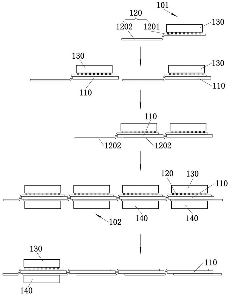
[0071] This embodiment provides a method for preparing a battery string, which is used for preparing the battery string. like figure 1 As shown, the battery string includes a plurality of battery sheets 110 , and two adjacent battery sheets 110 are connected in series by welding ribbons 120 . The welding strip 120 includes a front welding section 1201 and a back welding section 1202. The front welding section 1201 is fixed on the front of the previous cell 110 and is connected to the grid lines on the front of the cell 110. The back welding section 1202 is fixed to the latter cell 110. on the backside of the battery sheet 110 and connected to the back electrode on the backside of the battery sheet 110 to realize the series connection of the battery sheet 110 . In this embodiment, the upper surface of the battery sheet 110 is defined as the front surface of the battery sheet 110 , and the lower surface of the battery sheet 110 is defined as the back surface of the battery surf...

Embodiment 2

[0095] This embodiment provides a battery string welding device, which can use the battery string preparation method in the first embodiment.

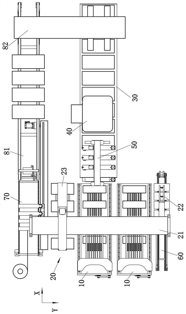
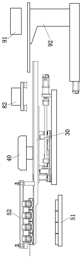
[0096] like figure 2 and image 3 As shown, the battery string laying equipment includes a laying platform 10 , a grabbing device 20 , a conveying device 30 , a lower mold supply device 50 and a welding device 40 . The grasping device 20 is used for grasping the battery sheet 110 , the welding tape 120 and the upper pressing tool 130 and placing it on the laying platform 10 , so that the welding tape 120 and the upper pressing tool 130 are stacked on the battery sheet 110 to form the laying unit 101 . The laying platform 10 is used to carry the laying units 101, and can stack the laying units 101, so that the back of the battery slices 110 in the subsequent laying unit 101 is placed on the back welding section 1202 in the previous laying unit 101; the lower mold The supply device 50 is used for providing the lower mold 140 to the ba...


PUM


Abstract

The invention belongs to the technical field of solar cells, and discloses a cell string preparation method and cell string welding equipment. The battery string preparation method comprises the steps that S1, a welding strip and an upper pressing tool are stacked on a battery piece to form a laying unit, the upper pressing tool and the front face welding section of the welding strip are sequentially stacked on the battery piece, and the back face welding section extends out of the surface of the battery piece; s2, the laying units are stacked, so that the back face of the next battery piece is arranged on the back face welding section of the previous laying unit; s3, laying a lower mold, enabling the lower mold to enable the back welding section in the previous laying unit to abut against the back of the battery piece in the next laying unit, and enabling the laying units and the corresponding lower mold to form a welding unit; s4, the laying unit and the lower mold are transferred to a heating station together; s5, the heated welding unit is transferred to a cooling station to be cooled, so that the welding strip is fixed to the two adjacent battery pieces; and when the welding unit at the front end is cooled, the steps from S1 to S4 are carried out at the rear end at the same time, so that the battery string production efficiency is improved.

Description

technical field [0001] The invention relates to the technical field of solar cells, in particular to a battery string preparation method and battery string welding equipment. Background technique [0002] When the battery string is welded, the welding tape needs to be arranged on the surface of the battery sheet in advance, and then the welding tape and the surface of the battery sheet are electrically connected by heating. The surface of the solder ribbon is usually covered with a tin layer, which is connected to the metal pads on the surface of the cell after being heated and melted. However, since the welding interconnection requires sufficient heating and cooling time, in order to avoid moving the battery string before the tin liquid is completely solidified, the welding tape on the battery string is not firmly bonded, resulting in the dislocation of the welding tape or the phenomenon of virtual welding and missing welding. It is necessary to wait. After a long cooling ...

Claims


Application Information

Patent Timeline
IPC IPC(8): B23K37/00H01L31/18
CPCB23K37/00B23K37/003H01L31/188B23K2101/36Y02P70/50Y02E10/50
Inventor 陈世庚路倩忠徐嘉航
Owner 江苏小牛自动化设备有限公司
Why Eureka
Try Eureka