Fuel supply device

A fuel supply device and fuel technology, applied in fuel injection devices, liquid fuel feeders, low-pressure fuel injection, etc., can solve the problems of increased components, inability to achieve low cost, complicated piping layout, etc., and achieve simplified piping Layout, component parts reduction, cost reduction effect

A fuel supply device and fuel technology, applied in fuel injection devices, liquid fuel feeders, low-pressure fuel injection, etc., can solve the problems of increased components, inability to achieve low cost, complicated piping layout, etc., and achieve simplified piping Layout, component parts reduction, cost reduction effect

CN101737213BActive Publication Date: 2013-03-06MITSUBISHI ELECTRIC CORP

Image

  • Fuel supply device
  • Fuel supply device
  • Fuel supply device

Examples


Embodiment Construction

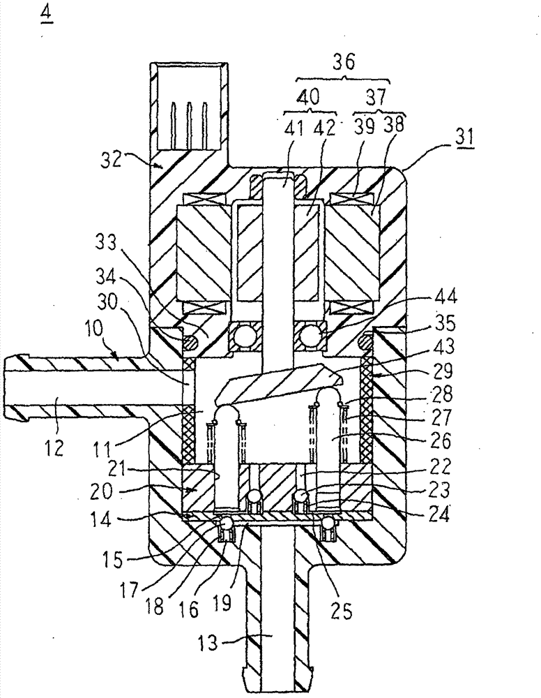
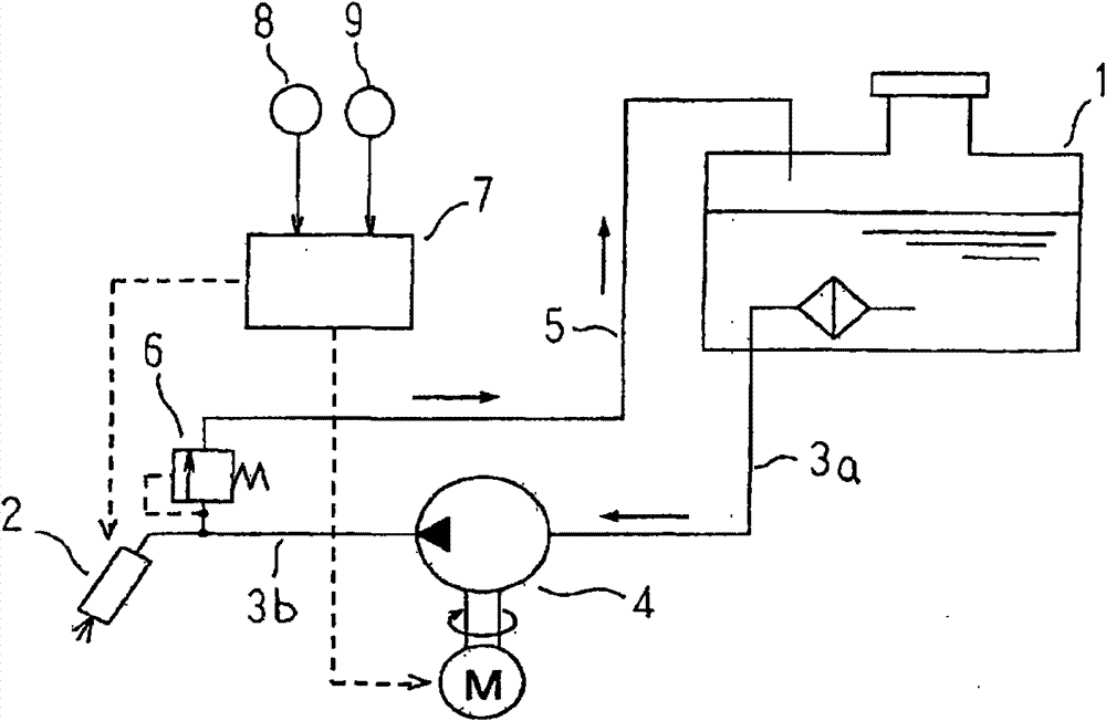
[0024] figure 1 is a diagram showing a system configuration of a fuel supply device according to an embodiment of the present invention, figure 2 It is a sectional view showing the structure of a fuel pump of a fuel supply device according to an embodiment of the present invention, image 3 It is a sectional view of main parts showing the structure of the pressure regulator device of the fuel supply system according to the embodiment of the present invention, Figure 4 It is a figure explaining the operation|movement of the pressure adjustment device of the fuel supply system which concerns on one Embodiment of this invention.

[0025] exist figure 1 Among them, the fuel supply device includes: a fuel tank 1; a fuel injection valve 2 that injects fuel toward an intake pipe (not shown) of the engine; the fuel that is sucked into the fuel tank 1 through a low-pressure pipe 3a, and injected toward the fuel through a high-pressure pipe 3b The fuel pump 4 that pumps fuel throug...


PUM


Abstract

The device has a pressure regulating device (6) i.e. poppet valve, provided such that fuel pressure is achieved within a high pressure line (3b). A fuel pump control unit (7) computes necessary fuel ejection rate while computing discharge flow rate that is added to necessary engine fuel rate. The engine fuel rate is computed based on engine operating condition that is detected by an air flow measuring device (8) and a crank angle sensor (9) to control engine rotating speed of a fuel pump (4) i.e. piston pump, for ejaculating the computed fuel ejection rate.

Description

technical field [0001] The present invention relates to a fuel supply device for an engine, and particularly relates to a technology capable of simply controlling fuel pressure. Background technique [0002] In a conventional fuel supply device, a pressure detection device is installed to detect the pressure of the fuel pressure-fed from the fuel pump to the fuel injection valve, and the required discharge amount of the fuel pump is determined based on a comparison between the fuel pressure target value and the actual fuel pressure. The fuel pump is driven and controlled for the required discharge amount (for example, refer to Patent Document 1). [0003] Patent Document 1: Japanese Patent Laid-Open No. 06-147047 [0004] In the conventional fuel supply device, a pressure detection device for measuring fuel pressure as a control parameter is required, and thus there are problems in that the number of components increases, cost reduction cannot be achieved, and piping arrang...

Claims


Application Information

Patent Timeline
06 Mar 2013
Publication
CN101737213B
IPC
F02M37/00; F02M37/08
CPC
F02D2200/0616; F02M69/02; F02D41/3082; F02M37/08; F02M37/0052
Inventors
η“œη”Ÿζ‹“δΉŸ; ε€§θ₯Ώε–„彦