Fast hydraulic change-over valve

A reversing valve and hydraulic technology, applied in the field of hydraulic control, can solve the problems of slowing down the opening speed of the hydraulic reversing valve, increasing the spring force of the hydraulic reversing valve, and long reset time, so as to save installation space and reduce The effect of spring force and fast return speed

Active Publication Date: 2011-11-09
ZHEJIANG UNIV
View PDF0 Cites 0 Cited by
  • Summary
  • Abstract
  • Description
  • Claims
  • Application Information

AI Technical Summary

Problems solved by technology

[0002] Most traditional hydraulic directional valves use return springs for reset. For high-response applications, in order to speed up the reset speed of the spool of hydraulic directional valves, it is necessary to increase the spring stiffness of the return spring. However, increasing the stiffness of the return spring will increase the hydraulic pressure. The spring force that needs to be overcome when the hydraulic reversing valve is opened, thus slowing down the opening speed of the hydraulic reversing valve, so the opening and reset speeds of the traditional hydraulic reversing valve are often contradictory, and because the traditional hydraulic reversing valve When it is in the open position, the return spring is compressed to the limit position, so the valve core needs to move for a long empty stroke when the hydraulic reversing valve is reset, resulting in a long reset time and slow reversing speed

Method used


Image

  • Fast hydraulic change-over valve
  • Fast hydraulic change-over valve
  • Fast hydraulic change-over valve

Examples


Embodiment 1

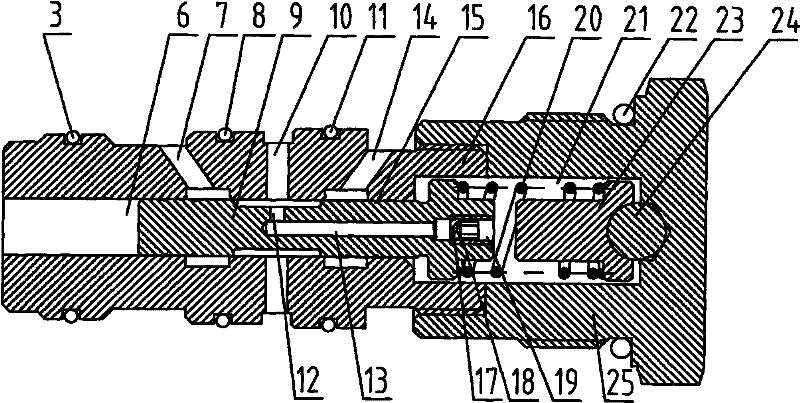
[0021] Such as figure 1 , Figure 4 , Figure 5 As shown, the quick hydraulic reversing valve of the present invention mainly includes a valve body 16 and a sleeve 25 . One end of valve body 16 is shaped on external thread (in Figure 1 to Figure 3 Among them, the external thread is at the right end of the valve body 16), the inside of the sleeve 25 is correspondingly processed with a groove and an internal thread is formed in the groove, so that the valve body 16 and the sleeve 25 are threadedly connected, and the valve body 16 The end face that is shaped on one end of external thread is close to the groove face of sleeve 25. A through hole is set inside the valve body 16 as the valve hole 6, and the valve core 9 is installed in the valve hole 6. The inner diameter of the valve hole 6 is matched with the outer diameter of the valve core 9. When the hydraulic control reversing valve is working, the valve The core 9 reciprocates left and right in the valve hole 6 to realize...

Embodiment 2

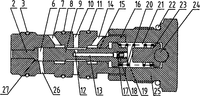
[0024] Such as figure 2 As shown, the end of the valve hole 6 away from the external thread (in figure 2 , that is, the left end of the valve hole 6) is stepped, and the stepped surface 27 of the valve hole 6 divides the end valve hole 6 into two parts. Among them, such as figure 2 As shown, the inner diameter of the valve hole on the left side of the stepped surface 27 is smaller than the inner diameter of the valve hole on the right side of the stepped surface 27, and a control push rod 2 is built in the valve hole on the left side of the stepped surface 27. The control push rod 2 is in clearance fit with this part of the valve hole 6; the inner diameter of the valve hole on the right side of the stepped surface 27 is larger, and a valve core 9 is built in it. As a preferred embodiment of the present invention, the control push rod 2 is also provided with a shoulder, which is located in the valve hole on the right side of the stepped surface 27, and the shoulder portion...

Embodiment 3

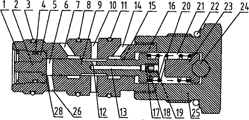
[0026] Such as image 3 As shown, further, at the end of the valve body 16 away from the external thread (in image 3 , which is the left end of the valve hole 6) is provided with a counterbore, and a support guide sleeve 5 is sealed and fixed on the inner wall of the counterbore. The center hole of the support guide sleeve 5 communicates with the valve hole 6 and is coaxial, and the support guide sleeve The center hole of 5 has a built-in control push rod 2, and the control push rod 2 is matched with the center hole of the support guide sleeve 5. When installing, the control push rod 2 is put into the center hole of the support guide sleeve 5 and integrated into the valve body. In the counterbore of 16, circlip 1 is installed on the outside of support guide sleeve 5, is used for fixing support guide sleeve 5, prevents loosening, and O type ring 4 is housed on the support guide sleeve, is used for sealing oil. On the wall of the valve body 16, there is also an oil drain cavit...


PUM


Abstract

The invention discloses a fast hydraulic change-over valve which comprises a valve body, a sleeve and a valve core; the valve core is arranged in the valve hole of the valve body; one end of the valve body is provided with an external thread and connected with the thread of the sleeve; the sleeve is provided with a spring cavity, the spring cavity is internally provided with a spring, and the spring is also arranged in the valve hole and contacted with the valve core; the wall of the valve body is provided with an oil inlet cavity, a working oil cavity and an returning cavity which are all communicated with the valve hole and arranged in sequence along the direction from the end provided with the external thread to the other end far away from the external thread; the valve core is provided with blind holes along the central axis of the valve core beginning from the end face opposite to the spring cavity; the shaft neck of the valve core is provided with radial holes communicated with the blind holes, the entrances of the blind holes are in thread connection with damping thread plugs, and the damping thread plugs are internally provided with throttle holes. The invention has the advantages that the valve core can be fast reset, and has short motion distance during resetting; the requirement on rigidity of the spring is low, and the valve core opening speed is accelerated; the volume of the control cavity is reduced, and the valve core has fast change-over speed; the structure is simple, the assembly and disassembly are convenient, and the assembly space is saved efficiently.

Description

technical field [0001] The invention relates to a hydraulic reversing valve, which belongs to the field of hydraulic control. Background technique [0002] Most traditional hydraulic directional valves use return springs for reset. For high-response applications, in order to speed up the reset speed of the spool of hydraulic directional valves, it is necessary to increase the spring stiffness of the return spring. However, increasing the stiffness of the return spring will increase the hydraulic pressure. The spring force that needs to be overcome when the hydraulic reversing valve is opened, thus slowing down the opening speed of the hydraulic reversing valve, so the opening and reset speeds of the traditional hydraulic reversing valve are often contradictory, and because the traditional hydraulic reversing valve When it is in the open position, the return spring is compressed to the limit position, so the valve core needs to move for a long empty stroke when the hydraulic ...

Claims


Application Information

Patent Timeline
Patent Type & Authority Patents(China)
IPC IPC(8): F15B13/02F16K31/12
Inventor 魏建华朱旭岳艺明高天翼
Owner ZHEJIANG UNIV
Why Eureka
Try Eureka