Composite bearing member, manufacturing method of composite bearing member, bearing device and rotary electrical machine

一种复合轴承、制造方法的技术,应用在轴承元件、轴承、轴和轴承等方向,能够解决功率限制、生产成本增加、昂贵等问题

Active Publication Date: 2010-06-16
KK TOSHIBA
View PDF1 Cites 6 Cited by
  • Summary
  • Abstract
  • Description
  • Claims
  • Application Information

AI Technical Summary

Problems solved by technology

[0011] When bearings for hydroelectric generators are produced, for example, by using the above-mentioned conventional method of combining resin materials and metal materials, the process of combining under vacuum is extremely expensive because the total weight of bearing base materials ranges from several hundred kilograms to several tons vary, and the cost of production will also increase
In addition, the power of vacuum equipment is also limited, and production under vacuum may sometimes be difficult

Method used


Image

  • Composite bearing member, manufacturing method of composite bearing member, bearing device and rotary electrical machine
  • Composite bearing member, manufacturing method of composite bearing member, bearing device and rotary electrical machine
  • Composite bearing member, manufacturing method of composite bearing member, bearing device and rotary electrical machine

Examples


Embodiment 1

[0095] In the actual embodiment 1, the composite bearing member 10 is combined with Figure 2A-2E Fabricated in a similar manner to the first fabrication method shown in .

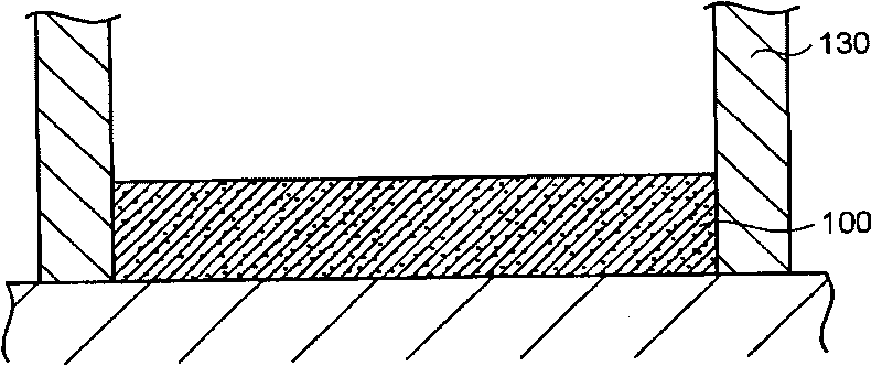
[0096] In the following, reference will be made to Figure 2A-2E A method of manufacturing the composite bearing member 10 used in Practical Example 1 will be described.

[0097] First, prepare resin particles 100 made of PTFE resin with an average particle diameter of 5 μm. It should be noted that the average particle size mentioned refers to the median value of the particle size. The average particle size is measured by a laser diffraction particle size distribution measurement method. Hereinafter, the meaning and measuring method of the average particle diameter are the same as those indicated above.

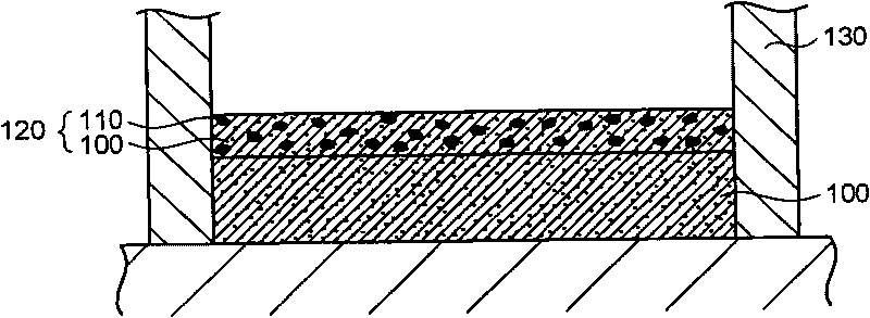
[0098] In addition, metal particles 110 made of a tin-copper-silver alloy (Sn-0.5 wt. % Cu-3.0 wt. % Ag) are prepared to be included in the composition-graded layer 60 . Here, the average particle di...

Embodiment 2

[0115] In the actual example 2, using the Figures 3A-3G The second manufacturing method shown produces composite bearing member 10 similar to the manufacturing method.

[0116] In the following, reference will be made to Figures 3A-3G A method of manufacturing the composite bearing member 10 used in Practical Example 2 will be described.

[0117] First, resin particles 100 made of PTFE resin having an average particle diameter of 5 μm are prepared. In addition, metal particles 111 made of a first metal material having a melting point lower than a sintering point at which resin particles 100 are sintered are prepared. The metal particles 111 are used to form pores to be contained in the composition-graded layer 60 into which the second metal material penetrates.

[0118] Here, the average particle diameter of the metal particles 111 used to form the metal material containing layer 61 is 25um, the average particle diameter of the metal particles 111 used to form the metal m...


PUM


Abstract

A composite bearing member 10 includes: a bearing sliding material 20 whose surface contacts a rotating portion; a bearing base material 30 made of a material different from a material constituting the bearing sliding material 20; and a joining layer 40 joining the bearing sliding material 20 and the bearing base material 30. Further, the bearing sliding material 20 has a sliding layer 50 sliding the rotating portion on a surface. Furthermore, the bearing sliding material 20 has, between the sliding layer 50 and the joining layer 40, a composition graded layer 60 which dispersedly contains the same metal material as a metal material constituting the joining layer 40 and in which a content of the metal material is increased toward the joining layer 40.

Description

[0001] Related Application Cross Reference [0002] This application is based on and claims priority from prior Japanese Patent Application No. 2008-295184 filed on November 19, 2008; the entire contents of which are hereby incorporated by reference. technical field [0003] The present invention relates to a composite bearing member used in a rotating electric machine and the like, a method of manufacturing the composite bearing member, a bearing device having the composite bearing member, and a rotating electric machine having the bearing device. Background technique [0004] In recent years, with the development of industrial technology, various types of bearings are required to cope with high-speed rotating shafts and high surface pressure. Usually white metals (eg Type I: tin antimony copper alloy: 88-92 wt% Sn, 5-7 wt% Sb, 3-5 wt% Cu) are used as bearing material. However, because such soft metal materials have problems such as low melting point, obvious weakening of ...

Claims


Application Information

Patent Timeline
Patent Type & Authority Applications(China)
IPC IPC(8): F16C17/00F16C33/20F16C17/26H02K5/167
CPCF16C33/12B22F7/08F16C17/06F16C33/203F16C33/208F16C2300/14F16C2300/34Y10T428/12021F16C2240/60F16C2240/06F16C2208/02F16C2208/58
Inventor 龙坦桐久里裕二南波聪向井一马
Owner KK TOSHIBA
Why Eureka
Try Eureka