

Method for paving internal concrete distributed sensing fibers
A laying method and sensing optical fiber technology, applied in the direction of optical fiber/cable installation, using optical devices, thermometers with physical/chemical changes, etc., can solve the problems that distributed sensing optical fibers cannot be embedded in concrete, and achieve effective monitoring Effects of structural strain and temperature, construction convenience, and stable health monitoring
Inactive Publication Date: 2010-06-16
ZHEJIANG UNIV
View PDF0 Cites 15 Cited by
- Summary
- Abstract
- Description
- Claims
- Application Information
AI Technical Summary
Problems solved by technology
The invention provides a method for laying distributed sensing optical fibers in concrete, which is not only convenient for construction, but also solves the problem that distributed sensing optical fibers cannot be embedded in concrete in the field of civil engineering health monitoring, and realizes distributed sensing in concrete Long-distance lossless laying of optical fiber
Method used
View moreImage
Smart ImageViewing Examples

Examples
Embodiment Construction
Login to View More PUM
| Property | Measurement | Unit |
|---|---|---|
| length | aaaaa | aaaaa |
| length | aaaaa | aaaaa |
Abstract
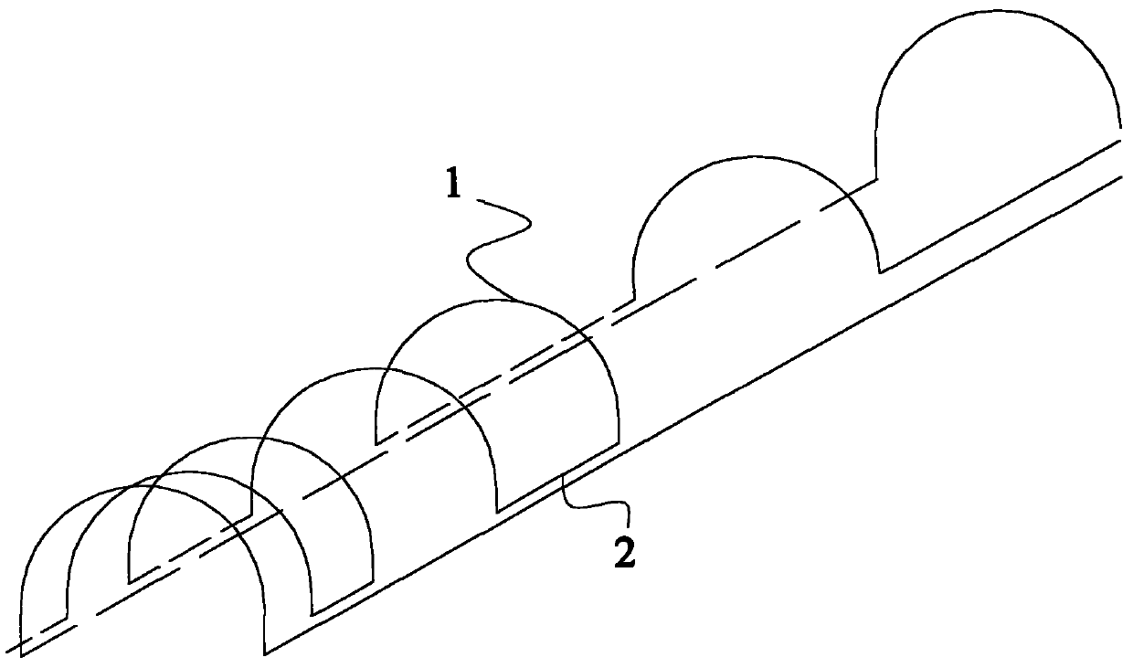
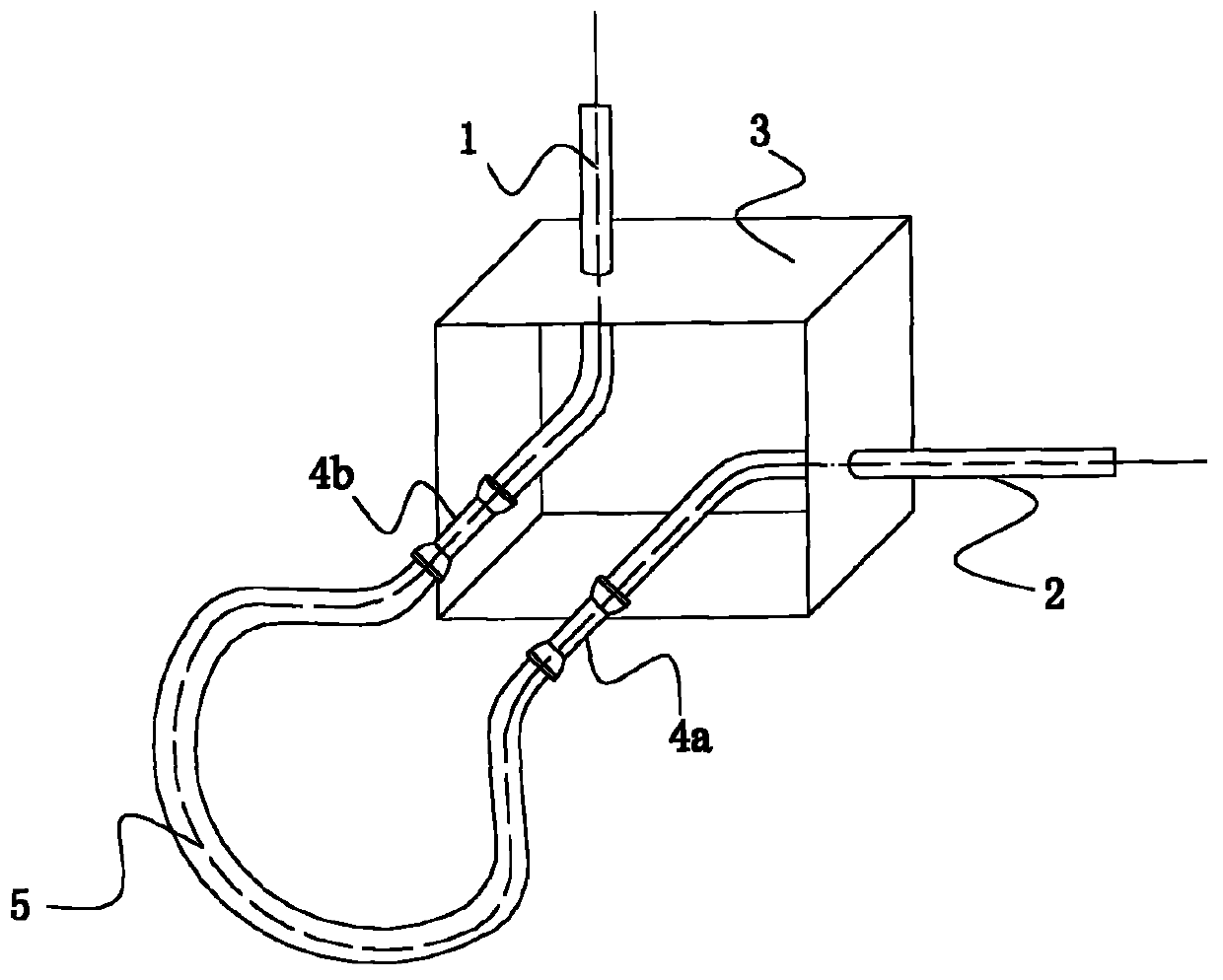
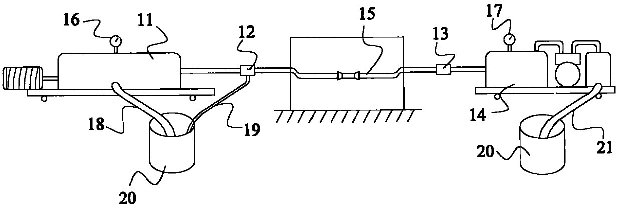
The invention discloses a method for paving internal concrete distributed sensing fibers, which comprises the following steps: A) checking and cleaning a fiber conduit embedded in the concrete; B) blowing the sensing fibers into the fiber conduit through a fiber gas blowing port; C) selecting a grouting section, injecting slurry into a grouting port of the grouting section, closing a slurry outlet of the grouting section after the slurry is full of the grouting section, and keeping the slurry in the grouting section for 3 to 5 minutes under the pressure of between 1.0 and 1.5MPa so as to fix the sensing fibers in the fiber conduit; and D) circularly operating the step C) till the grouting of all the grouting sections is finished. The method achieves quick and lossless pavement for the long-distance distributed sensing fibers, solves the difficult problem that the structure monitoring field cannot embed the distributed sensing fibers into the concrete, ensures the distributed fiber sensing technology to monitor the structural strain and temperature more effectively, and realizes structural long-term and stable healthy survey.
Description
technical field The invention relates to the field of civil engineering health monitoring, in particular to a method for laying distributed sensing optical fibers inside concrete. Background technique According to the relationship between Brillouin frequency shift and fiber strain and temperature, distributed fiber optic sensing technology, when the strain or temperature along the fiber changes, the frequency of backscattered light in the fiber will drift. The frequency drift has a good linear relationship with the change of fiber strain and temperature, so the distribution information of temperature and strain along the fiber can be obtained by measuring the frequency drift of Brillouin backscattering in the fiber. Distributed optical fiber sensing technology is currently the most cutting-edge technology in the world. Compared with traditional monitoring technology, it has the following advantages: (1) Distributed: A monitoring network with a certain scale can be formed b...
Claims
Login to View More Application Information
Patent Timeline
 Patent Type & AuthorityApplications(China)
IPC IPC(8): G02B6/52G01K11/32G01B11/16G01K11/322
Inventor金伟良何勇毛江鸿
OwnerZHEJIANG UNIV