
Display and method for assembling same

A display and assembly technology, applied in the direction of instruments, optics, electrical components, etc., can solve the problems of increased heavy industry and maintenance costs, difficult handling, difficult production control, etc., to increase decorative effects and aesthetics, and reduce packaging and transportation costs , Improve the effect of product yield

Inactive Publication Date: 2010-06-16
UNIHAN CORPORATION
View PDF0 Cites 1 Cited by
  • Summary
  • Abstract
  • Description
  • Claims
  • Application Information

AI Technical Summary

Problems solved by technology

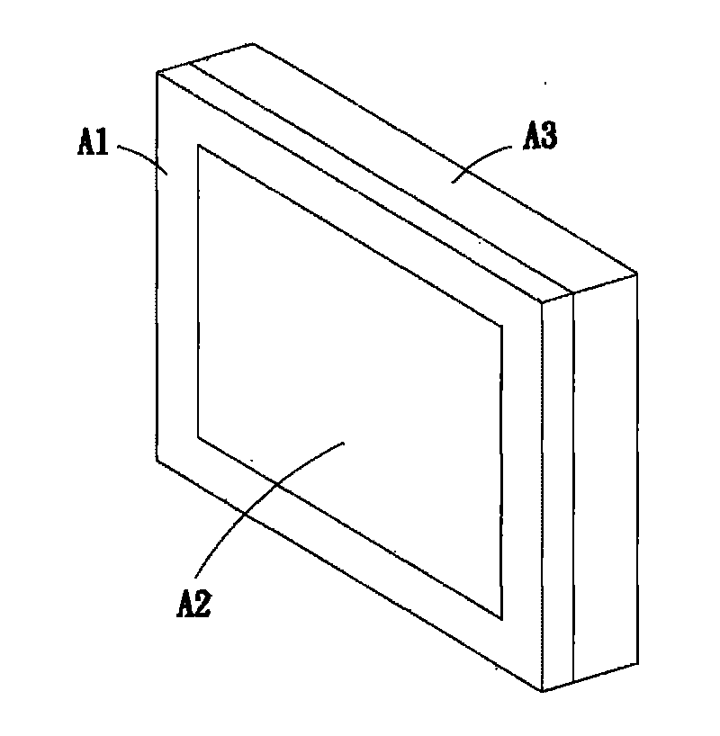
[0003] As the size of the display increases day by day, although the above-mentioned display is simple in structure and easy to assemble, it must spend a lot of cost and time to develop an injection molding mold for the integrally formed front frame A1 and rear case A3, resulting in the cost of the mold. It remains high, which leads to large material loss and increased component costs. Due to the large volume, production control is not easy, resulting in low forming yields of the front frame A1 and the rear shell A3, which greatly increases the cost of rework and maintenance, and the product interoperability is small. Inventory control is not easy
In addition, due to the increasing size of the front frame A1 and the rear case A3, the packaging volume is large, which not only makes transportation more difficult, but also greatly increases the transportation cost.
Furthermore, the front frame A1 and the rear case A3 made of integral molding not only have a relatively monotonous appearance and shape, but also cannot have various color changes, which makes the decorative effect and aesthetics not good.

Method used


Image

  • Display and method for assembling same
  • Display and method for assembling same
  • Display and method for assembling same

Examples


Embodiment Construction

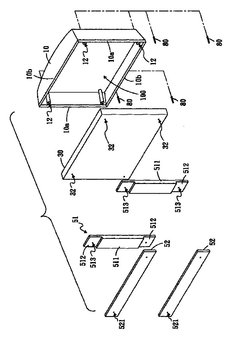
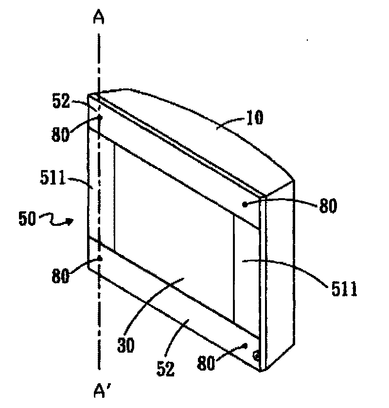
[0024] see figure 2 , image 3 , Figure 4A and Figure 4B As shown, the display disclosed in the first embodiment of the present invention includes a casing 10 , a display panel 30 , a front panel 50 , and a plurality of locking components 80 .

[0025] The casing 10 is generally rectangular, has two first sides 10a and two second sides 10b that are substantially perpendicular to each other, and forms an accommodating space 100. In addition, the casing 10 can be respectively pierced at four corners. Through hole 12 is established.

[0026] The display panel 30 is substantially rectangular and accommodated in the accommodating space 100 of the housing 10 . Here, the display panel 30 may be a liquid crystal display or a plasma display, but the present invention is not limited thereto. In addition, the display panel 30 can respectively define positioning holes 32 at the four end corners, and the positioning holes 32 and the through holes 12 are provided correspondingly.

...


PUM


Abstract

The invention discloses a display. The display comprises a shell, a display panel and a front panel, wherein the display panel is accommodated in the shell; the front panel is arranged on the shell to cover edges of the display panel, and comprises two first panel bodies and two second panel bodies; each first panel body comprises a main plate and two matching parts on two sides of the main plate; and the two second panel bodies are superposed on the matching parts. The invention also discloses a method for assembling the display.

Description

technical field [0001] The invention relates to a shell structure and its assembly method, in particular to a display and its assembly method. Background technique [0002] Currently common liquid crystal displays or plasma displays, such as figure 1 As shown, it is mainly composed of a front frame A1, a display A2 and a rear case A3, wherein the front frame A1 and the rear case A3 are integrally formed by plastic injection. When assembling, put the display A2 and other circuit devices (not shown) into the rear case A3, combine the front frame A1 and the rear case A3, and lock them together with screws A5 to accommodate the display A2 and Other circuit devices are between the front frame A1 and the rear case A3. [0003] As the size of the display increases day by day, although the above-mentioned display is simple in structure and easy to assemble, it must spend a lot of cost and time to develop an injection molding mold for the integrally formed front frame A1 and rear c...

Claims


Application Information

Patent Timeline
Patent Type & Authority Applications(China)
IPC IPC(8): G02F1/13H01J17/49H05K5/00
Inventor 吴佳宪陈镱仁吕三和
Owner UNIHAN CORPORATION
Learn More