Demarcation circuit breaker device and remote monitoring method thereof

A boundary circuit breaker and equipment technology, applied in the direction of circuit devices, emergency protection circuit devices, emergency protection devices for automatic disconnection, etc., can solve the problems of difficult monitoring and scattered distribution of boundary circuit breaker equipment

Inactive Publication Date: 2010-06-16
郑文秀
View PDF2 Cites 11 Cited by
  • Summary
  • Abstract
  • Description
  • Claims
  • Application Information

AI Technical Summary

Problems solved by technology

[0006] The second purpose of the present invention is to provide a remote monitoring method for boundary circuit breaker equi

Method used


Image

  • Demarcation circuit breaker device and remote monitoring method thereof
  • Demarcation circuit breaker device and remote monitoring method thereof
  • Demarcation circuit breaker device and remote monitoring method thereof

Examples


Embodiment 1

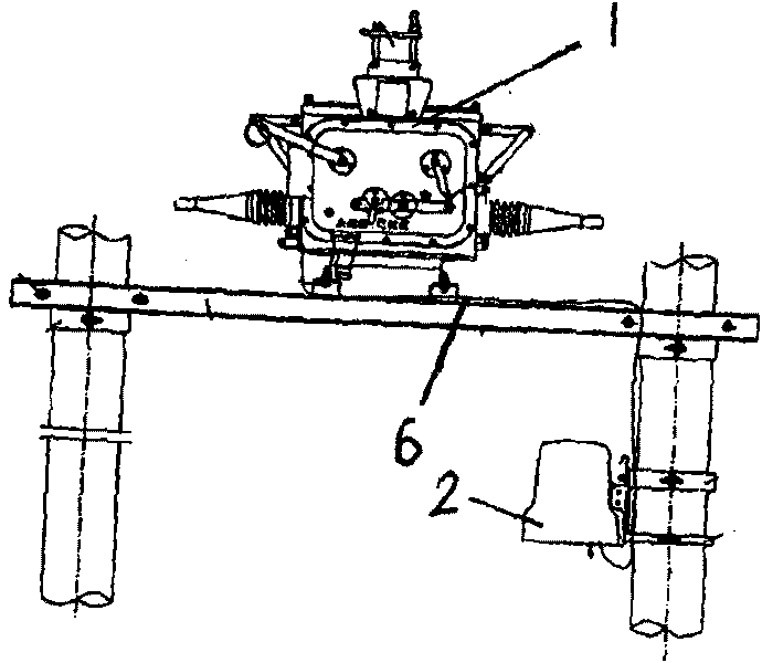
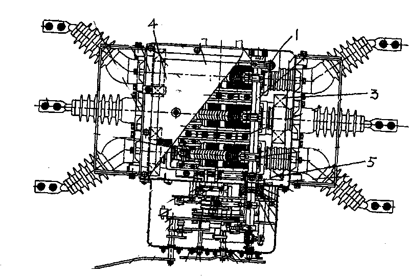
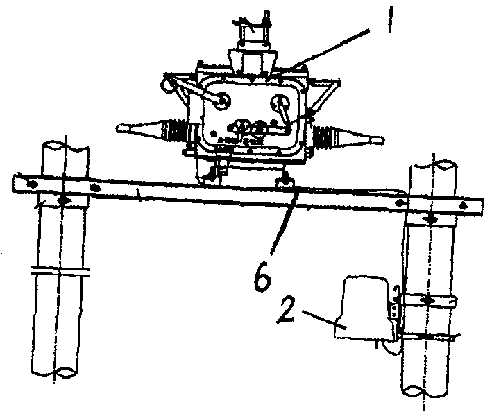
[0024] see figure 1 and figure 2 , a boundary circuit breaker device, which includes a high-voltage vacuum boundary circuit breaker body 1 and an intelligent protection terminal 2. The high-voltage vacuum boundary circuit breaker body 1 adopts the functions of hand, electric energy storage / hand, electric closing / hand, and electric opening. The high-voltage vacuum boundary circuit breaker body 1 has a built-in zero-sequence current transformer 3 and two current transformers 4, the transformation ratio of the zero-sequence current transformer 3 is 20 / 1, and the primary current is 0.1A-5A. The segment maintains a linear relationship, the rated load is 1Ω, the transformation ratio error under the rated load is less than 3%, the primary zero-sequence current is 400A, the effective value of the secondary output current is not less than 5A, and the rated short-time withstand current is 16KA, 20KA, 25KA, 4S, The transformation ratio of the current transformer 4 is 600 / 5, the rated l...

Embodiment 2

[0028] see figure 1 , a remote monitoring method for boundary circuit breaker equipment, the protection device in the boundary circuit breaker equipment automatically and accurately locates its own coordinates through the GPS satellite positioning system, and the GPRS communication module in the boundary circuit breaker equipment connects the power distribution line and the boundary circuit breaker equipment The real-time information of the high-voltage vacuum boundary circuit breaker body 1 is sent to the background monitoring system based on the GIS (Geographic Information System) display platform by using Internet.

[0029]The background monitoring system is composed of a switching center, a GPS clock, a web server, a hardware firewall and a data backup server. Data collection of protection terminals, fault reporting and fault SMS alarm; GPS clock: maintain the accuracy of the system clock at all times, and ensure the synchronization of intelligent protection terminal and s...


PUM


Abstract

The invention discloses a demarcation circuit breaker device, comprising a high-voltage vacuum demarcation circuit breaker body and an intelligent protection terminal, wherein the high-voltage vacuum demarcation circuit breaker body is internally provided with a zero sequence current mutual inductor and two current transformers; a voltage transformer is arranged at the power side of the high-voltage vacuum demarcation circuit breaker body; the intelligent protection terminal arranged on a field distribution line comprises a protection device for protecting the distribution line and measuring the operation state of the distribution line and a GPRS communication module; the protection device is directly connected with the high-voltage vacuum demarcation circuit breaker body by an omniseal airproof aviation connector and an outdoor sealing cable, and is connected with the GPRS communication module by a serial interface; and the operation power and the voltage signals of the intelligent protection terminal and the high-voltage vacuum demarcation circuit breaker body are all provided by the voltage transformer. The invention can be widely used in 10kV and 13 kV overground ring network lines as a sectionalizer switch and an interconnection switch, and can implement an automatic switching device deployed by ring network load.

Description

technical field [0001] The invention relates to an automatic switch device which can be used as segmental isolation switch and contact switch in the overhead ring network line of power system 10KV, 13KV city and rural distribution network, and can implement ring network load allocation. As a boundary switch (commonly known as a watchdog), it is used as a recloser and a sectionalizer in the feeder overhead distribution network, especially a boundary circuit breaker device. [0002] The invention also relates to a remote monitoring method for boundary circuit breaker equipment. Background technique [0003] The electric power industry is a technology-intensive and equipment-intensive industry, and its unique production and operation methods determine its informatization development model. From the initial focus on the automatic monitoring / monitoring of power plants and substations, to the special application of power business, mainly involving the use of power grid dispatchin...

Claims


Application Information

Patent Timeline
IPC IPC(8): H02H3/32H02H3/08H02H3/06H02H3/16H02J13/00
CPCY04S40/126Y04S40/127Y02E60/7853Y02E60/7861Y02E60/00
Inventor 郑文秀苏杭颜凯
Owner 郑文秀
Why Eureka
Try Eureka