

Methods and apparatus for a permanent magnet machine with an added air barrier
A permanent magnet motor and rotor technology, applied to synchronous motors with stationary armatures and rotating magnets, motors, transportation and packaging, etc., can solve the problems of increasing manufacturing complexity and cost, reducing motor torque, etc.
- Summary
- Abstract
- Description
- Claims
- Application Information
AI Technical Summary
Problems solved by technology
Method used
Image

Examples
Embodiment Construction
[0012] The following detailed description is merely illustrative in nature and is not intended to limit the invention or the application and uses of the invention. Furthermore, there is no intention to be bound by any expressed or implied theory presented in the preceding technical field, background, brief summary, or the following detailed description. The invention may be described herein in terms of functional and / or logical block components, and various process steps. It should be appreciated that these block components may be realized by a number of hardware, software, and / or firmware components configured to perform the specified functions. For the sake of brevity, this article does not describe in detail the common technologies and systems related to electric motors, magnetics, etc.
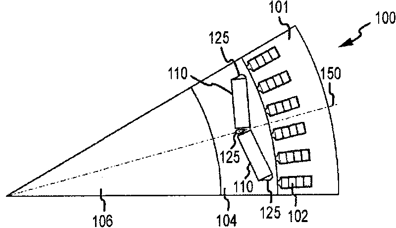
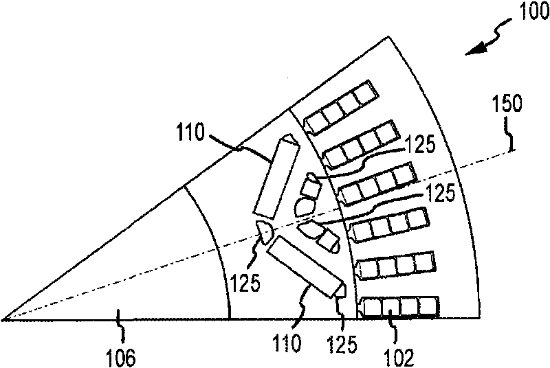
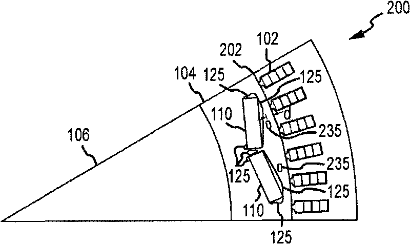
[0013] In general, the various embodiments relate to permanent magnet motors ("PM motors"), and more specifically, to interior permanent magnet motors ("IPM motors") that include rotor, ...
PUM
 Abstract
Description
Claims
Application Information