Centrifugal straight shaft rotary jet engine

A jet engine, centrifugal technology, applied in the direction of combustion engine, machine/engine, internal combustion piston engine, etc., can solve the problems of short life, high cost of crankshaft processing, large energy loss, etc., to improve service life, save energy loss, The effect of improving thermal efficiency

Inactive Publication Date: 2010-06-23
杨懋钧
View PDF0 Cites 0 Cited by
  • Summary
  • Abstract
  • Description
  • Claims
  • Application Information

AI Technical Summary

Problems solved by technology

Among them, the piston reciprocating engine has low effective thermal efficiency, while the convex triangular rotor engine is an externally convex triangular rotor. The three vertices of the triangular rotor are in close contact with the profile of the cylinder body, and three radial small elastic The sealing sheet is equipped with two arc-shaped lateral sealing strips and wave springs on both sides of the rotor, and a total of six arc-shaped lateral sealing strips and wave springs on three sides
The three small elastic seals installed on the three vertices of the triangular rotor are in line contact with the surface of the cylinder body, like three sharp knives scraping each other on the surface of the hard chrome plated surface, and the surface will quickly There will be wavy vibration wear, so the engine wears seriously and has a short life.
Due to the above reasons, rotary engines are generally used in racing cars and cannot be widely used.
[0003] Both of these engines use crankshafts, which are expensive to process, cause large vibrations during motion, and cannot increase the speed, so the horsepower is small and difficult to process.
The temperature of these two engines after work is as high as 1600K, and the pressure is about 5Kg / cm 2 , are all discharged in vain, and the energy loss is very large

Method used


Image

  • Centrifugal straight shaft rotary jet engine
  • Centrifugal straight shaft rotary jet engine
  • Centrifugal straight shaft rotary jet engine

Examples


Embodiment 1

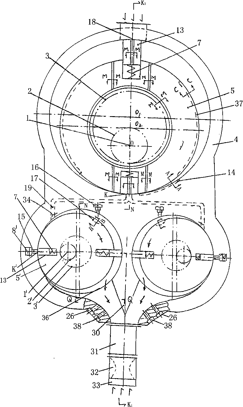
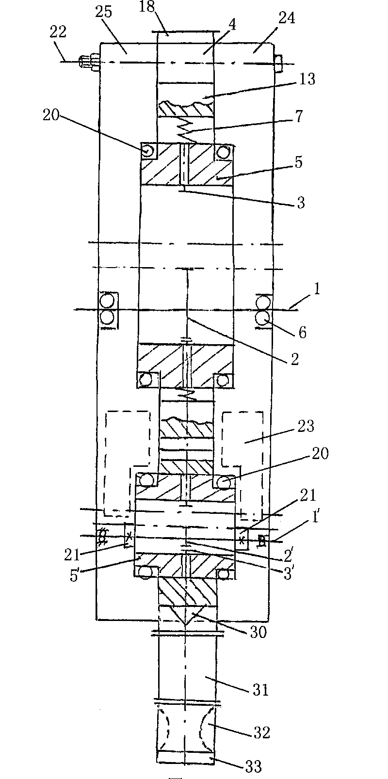
[0028] A centrifugal direct-axis rotor jet engine, comprising a main shaft 1, a rotor, a cylinder block 4, left and right cover plates (25, 24), an oil inlet 18, an exhaust port 33, left and right cover plates (25, 24 ) and the cylinder body 4 are fixed by fixing bolts 22; at least two rotors are arranged in the cylinder body 4, the cross section of the rotor is circular, the rotor is provided with a sliding seat, and the movement track of the rotor in the cylinder body 4 is a planetary track or a circular track . There are n sliding seats provided on the rotor, where n≥2 integers; the angles of the two adjacent sliding seats are equal.

[0029] Two rotors are arranged in the cylinder block 4 of this embodiment, and there are two sliding seats on each rotor. The rotor 5' is connected through a high-pressure oil inlet pipeline 19, the intake compression rotor 5 is arranged on the upper part of the cylinder body 4, and the chamber where the intake compression rotor 5 is located...

Embodiment 2

[0037] There are three rotors in the cylinder body 4, one air intake compression rotor 5, two power exhaust rotors 5', and two power exhaust rotors 5' are distributed symmetrically with the cylinder body 4 centerline. Others are with embodiment 1.

Embodiment 3

[0039] There are four rotors in the cylinder body 4, two air intake and compression rotors 5, two power exhaust rotors 5', two air intake compression rotors 5 and two power exhaust rotors 5' centered on the cylinder body 4 line symmetrical distribution. Others are with embodiment 1.

[0040] The working principle of the invention: After the oil is atomized and enters the intake compression rotor from the oil inlet, after being compressed, the intake compression rotor turns to the tangent point K and enters the high-pressure oil inlet pipeline through the dark channel. After pushing the reed valve, it enters the operating The spark plug in the chamber where the power exhaust rotor is located works, the reed valve closes, and the power exhaust rotor turns to the cylinder exhaust port to discharge the high-temperature gas in the chamber. At this time, the temperature drops to 1600K and the pressure is 5 atmospheres , in order to convert temperature and pressure into kinetic ener...


PUM


Abstract

The invention relates to engine, in particular to a centrifugal straight shaft rotary jet engine. The invention is realized by the way that: the centrifugal straight shaft rotary jet engine comprises a spindle, a rotor, a cylinder body, a left cover plate, a right cover plate, an oil inlet and an air exhaust, the cross section of the rotor is circular, the rotor is provided with a sliding seat, and the motion trail of the rotor in the cylinder body is planet trail or circular trace; the rotor is composed of an air suction compression rotor and a work done air exhaust rotor; and the air suction compression rotor and the work done air exhaust rotor are connected by a high pressure oil inlet pipeline. The invention has the advantages that: the shaft of rotary engine is changed into straight shaft from crank, cost is reduced, oscillation is eliminated, thermal efficiency is improved, cost is low, and horsepower is improved.

Description

technical field [0001] The invention relates to engines, in particular to a centrifugal direct-shaft rotor jet engine. Background technique [0002] At present, the engine is divided into two types, one is a piston reciprocating engine, and the other is a convex triangular rotor engine. Among them, the piston reciprocating engine has low effective thermal efficiency, while the convex triangular rotor engine is an externally convex triangular rotor. The three vertices of the triangular rotor are in close contact with the profile of the cylinder body. The sealing sheet is provided with two arc-shaped lateral sealing strips and wave springs on both sides of the rotor, and a total of six arc-shaped lateral sealing strips and wave springs on three sides. The three small elastic seals installed on the three vertices of the triangular rotor are in line contact with the surface of the cylinder block, like three sharp knives scraping each other on the surface of the hard chrome plat...

Claims


Application Information

Patent Timeline
Patent Type & Authority Applications(China)
IPC IPC(8): F02B53/02
CPCY02T10/17Y02T10/12
Inventor 杨懋钧
Owner 杨懋钧
Why Eureka
Try Eureka