Screw rod with rollers
A technology of roller screw and roller, applied in the direction of belt/chain/gear, mechanical equipment, transmission device, etc., can solve the problems of high wear and heat, high noise and high cost, achieve low friction, reduce manufacturing cost and The effect of running noise and low cost
Inactive Publication Date: 2010-06-23
徐众
View PDF0 Cites 7 Cited by
- Summary
- Abstract
- Description
- Claims
- Application Information
AI Technical Summary
Problems solved by technology
[0002] At present, compared with the traditional nut screw, the friction and heat are relatively large, the cost of the ball screw is high, the screw needs to be finely ground, and the noise is relatively high, and the planetary roller screw needs to process the tooth surface and the inner ring gear, and the cost is high. complex structure
Method used
View moreImage
Smart ImageViewing Examples

Examples
Embodiment Construction
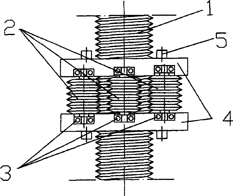
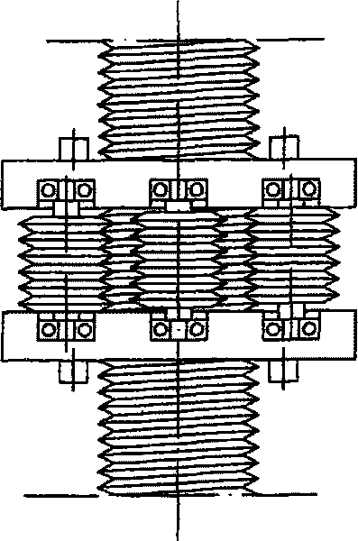
[0009] When the roller screw is in operation, the rotation of the screw (1) drives the meshed roller (2) to rotate and translate, and the roller (2) is supported by the bearings (3) at both ends to rotate and drives the bearing seat (4) to translate.
[0010] This kind of screw can be widely used in linear motion mechanisms driven by screw or ball screw, such as machine tools, woodworking machinery, medical and automation equipment.
Login to View More PUM
 Abstract
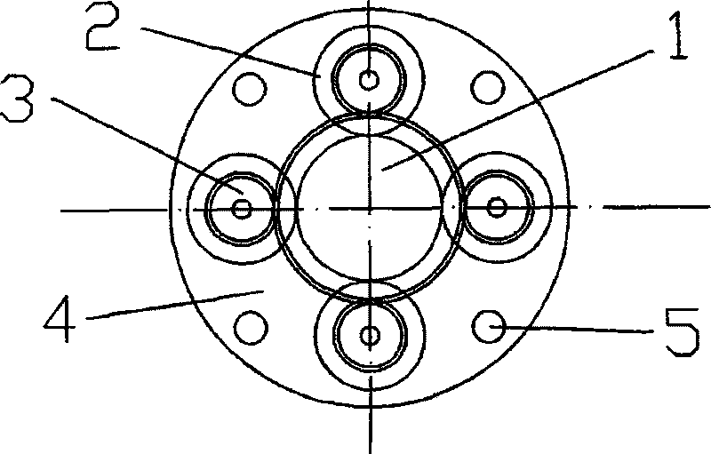
The invention relates to a screw rod with rollers, which comprises a screw rod, rollers, a bearing, a bearing pedestal and pin bolts, wherein the rollers are uniformly distributed on the circumference of the screw rod, both ends of the rollers are positioned in the bearing pedestal by the bearing, the bearing pedestal is fixed by the pin bolts, and the uniformly distributed rollers are distributed in parallel with an equal height difference in an axial direction and engaged with the threads of the long screw rod. During running, the rotation of the screw rod drives the engaged rollers to rotate and translate, and the rollers are supported by rolling bearings at both ends to rotate and drive the translation of the bearing pedestal. The screw rod can be widely used on straight-line motion mechanisms driven by a screw or transmitted by a ball screw, such as a machine tool, woodworking machinery, medical treatment and automation equipment.
Description
Technical field: [0001] A new type of roller screw can be widely used in linear drive systems of machine tools and various automation equipment. Background technique: [0002] At present, compared with the traditional nut screw, the friction and heat are relatively large, the cost of the ball screw is high, the screw needs to be finely ground, and the noise is relatively high, and the planetary roller screw needs to process the tooth surface and the inner ring gear, and the cost is high. complex structure. Invention content: [0003] In order to overcome the large friction and heat generated by the sliding friction between the nut and the screw, the design adopts the form of a roller, which meshes with the screw and rolls. The rotational motion is pure rolling, and the friction and wear of the screw are greatly reduced. It is suitable for long-term and reciprocating Movement body. [0004] attached figure 1 As shown, there are rollers (2) evenly distributed in the circu...
Claims
Login to View More Application Information
Patent Timeline
 IPC IPC(8): F16H25/22
CPCF16H25/2252
Inventor 徐众
Owner 徐众