Combustion control method for regenerative-combustion heat treat furnace

A technology of heat treatment furnace and thermal storage combustion, which is applied in the direction of combustion method, combustion control, and treatment of combustion products, which can solve the problems of heat treatment furnace heat utilization rate reduction and achieve the effect of preventing the heat utilization rate from greatly reducing

Active Publication Date: 2010-06-23
CHUGAI RO CO LTD
View PDF7 Cites 3 Cited by
  • Summary
  • Abstract
  • Description
  • Claims
  • Application Information

AI Technical Summary

Problems solved by technology

[0009] Here, as described above, when the combustion load is low, when the regenerative burners that are stopped are changed at a fixed period and the combustion time of each regenerative burner installed in the heat treatment furnace is equalized, the heat treatment The combustion time of the regenerative burner at a position nearer to the discharge part where a part of the combustion exhaust gas in the furnace is discharged to the outside of the heat treatment furnace is the same as the combustion time of the regenerative burner at a position farther from the discharge part, The high-temperature combustion exhaust gas generated by the combustion of the regenerative burner near the discharge part is immediately led out of the heat treatment furnace through the discharge part, and the heat utilization rate in the heat treatment furnace is greatly reduced. question

Method used


Image

  • Combustion control method for regenerative-combustion heat treat furnace
  • Combustion control method for regenerative-combustion heat treat furnace
  • Combustion control method for regenerative-combustion heat treat furnace

Examples


Embodiment Construction

[0039] Hereinafter, the combustion control method of the regenerative combustion type heat treatment furnace according to the embodiment of the present invention will be specifically described with reference to the drawings. In addition, the control method of the regenerative combustion type heat treatment furnace of this invention is not specifically limited to embodiment shown below, It can change suitably within the range which does not change the object of invention.

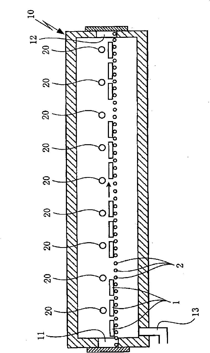
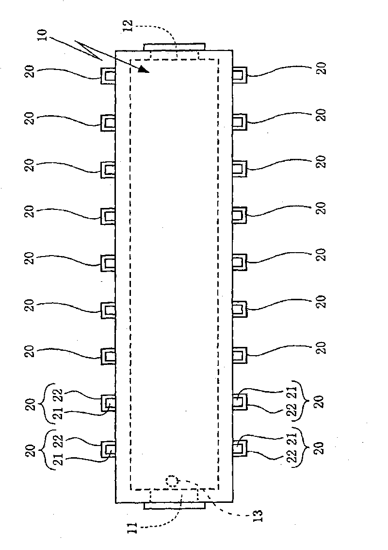
[0040] Here, if figure 1 As shown, in the present embodiment, the material to be processed 1 made of steel that is guided into the heat treatment furnace 10 from the inlet 11 of the heat treatment furnace 10 is transported into the heat treatment furnace 10 by the conveying roller 2 and heat-treated, and will be heat-treated as described above. The heat-treated material 1 to be processed is taken out of the heat treatment furnace 10 through the outlet 12 of the heat treatment furnace 10 .

[0041] In additi...


PUM


Abstract

In a regenerative-combustion heat treat furnace which is provided with plural pairs of regenerative burners and an exhaust portion for discharging a part of the combustion exhaust gas in the heat treat furnace to the outside of the heat treat furnace, the combustion and the combustion stop of each pair of regenerative burners are properly controlled according to a combustion load in the heat treat furnace and the drop of utilization rate of heat in the heat treat furnace is suppressed. In a regenerative-combustion heat treat furnace 10 provided with plural pairs of regenerative burners 20 and an exhaust portion 13 for discharging a part of the combustion exhaust gas in the heat treat furnace 10 to the outside of the heat treat furnace, the plural pairs of regenerative burners are controlled by switching the paired regenerative burners between the combustion and the combustion stop according to a combustion load in the heat treat furnace. In this control, stop time is defined to be the longest at a regenerative burner pair adjacent to the exhaust portion and progressively decreased therefrom.

Description

[0001] Associate application [0002] This application claims priority based on Japanese Patent Application No. 2008-319593. technical field [0003] The present invention relates to a heat storage combustion type heat treatment furnace, which is provided with a plurality of pairs of heat storage chambers including a burner portion having a fuel injection nozzle and a heat storage chamber for accommodating a heat storage material along the moving direction of the material to be processed in the heat treatment furnace. The regenerative burner (burner) is equipped with a discharge part that discharges a part of the combustion exhaust gas in the heat treatment furnace to the outside of the heat treatment furnace. Among each pair of regenerative burners, one regenerative burner passes through the regenerator Combustion air is guided to the burner part, and fuel gas is injected from the fuel injection nozzle of the burner part for combustion, while the other regenerative burner gui...

Claims


Application Information

Patent Timeline
Patent Type & Authority Applications(China)
IPC IPC(8): F27B9/40F27B9/36
CPCF23N5/203F23N2037/02F27B9/36F23C5/08F23N2031/30F27B9/30F27D99/0033F23L15/02F27D17/004F23N2027/10F23N2227/10F23N2231/30F23N2237/02Y02E20/34F23D14/66F23J11/00
Inventor 木本康之上岛啓利
Owner CHUGAI RO CO LTD
Why Eureka
Try Eureka