Wind speed and direction real-time measuring method and device of high-altitude sky-parking aircraft

A technology for real-time measurement of wind speed and direction, applied in the fields of flight control and aviation measurement and control, can solve the problems that low-speed aircraft cannot provide real-time wind speed and wind direction information for flight control, and achieve the effects of easy implementation, accurate measurement, and high measurement accuracy

Inactive Publication Date: 2010-06-23
ACAD OF OPTO ELECTRONICS CHINESE ACAD OF SCI
View PDF0 Cites 35 Cited by
  • Summary
  • Abstract
  • Description
  • Claims
  • Application Information

AI Technical Summary

Problems solved by technology

[0021] In view of this, the main purpose of the present invention is to provide a kind of method and device for real-time measurement of wind speed and direction of high-altitude airborne aircraft that can be directly used to provide real-time wind speed and wind direction information needed for flight control for low-speed aircraft, to solve the inability of the prior art The problem of providing real-time wind speed and wind direction information required for flight control to low-speed aircraft

Method used


Image

  • Wind speed and direction real-time measuring method and device of high-altitude sky-parking aircraft
  • Wind speed and direction real-time measuring method and device of high-altitude sky-parking aircraft
  • Wind speed and direction real-time measuring method and device of high-altitude sky-parking aircraft

Examples


Embodiment Construction

[0049]Various details involved in the technical solution of the present invention will be described in detail below in conjunction with the accompanying drawings. It should be pointed out that the described embodiments are only intended to facilitate the understanding of the present invention, rather than limiting it in any way.

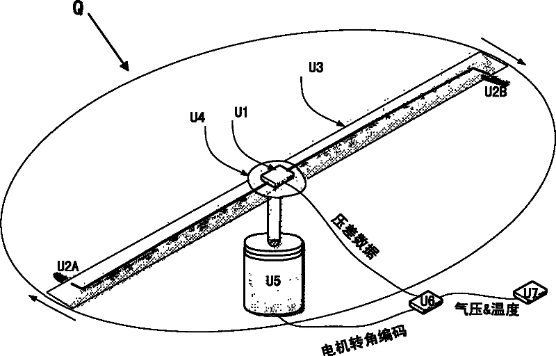
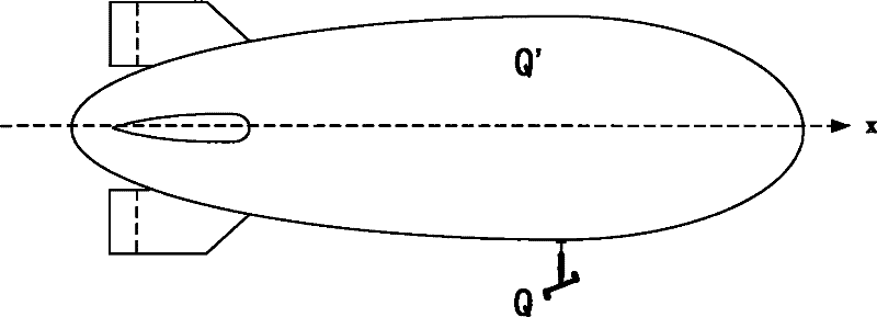
[0050] Measuring device Q of the present invention is as attached figure 1 as shown, figure 2 It is a schematic diagram of installation of measuring device Q of the present invention on high-altitude airborne aircraft Q';

[0051] The device Q of the present invention consists of a main device and accessories. The main device includes: differential pressure sensor U1, pressure measuring probe U2 includes: first pressure measuring probe U2A and second pressure measuring probe U2B, rigid rotary rod U3, sensor mounting plate U4, brushless motor U5 and its controller and microprocessor device U6. Attachment U7 includes a barometer and a temperature ...


PUM


Abstract

The invention provides a wind speed and direction real-time measuring method and a device of a high-altitude sky-parking aircraft. The method is composed of a measuring device and a wind speed and direction extraction algorithm, wherein, the measuring device is a rigid rotary rod which is driven by a brushless motor and rotates at a constant angular speed, two ends of the rigid rotary rod are provided with pressure measuring probes which are connected to a differential pressure transducer. When wind blows to the rigid rotary rod which constantly rotates, the pressure difference between the two pressure measuring probes is a periodic cosine signal, and the amplitude of the signal is in direct proportion to the wind speed, and the phase position of the signal contains wind angle information. By adopting the extraction algorithm of the invention, wind speed and direction information can be extracted from the differential pressure signal. The invention is characterized in that the amplitude of the differential pressure signal is in direct proportion to the product of atmospheric density and the linear speed of a rotary arm at the predetermined wind speed. Thus, in the invention, larger signal amount can be obtained under lower atmospheric density by reasonably selecting the rotating speed of the rigid rotary rod and the length of the rotary arm so as to reliably extract the wind speed and direction information.

Description

technical field [0001] The invention is mainly used for flight control of high-altitude aircraft. Its role is to provide real-time relative wind speed / wind direction information (airspeed / sideslip angle) and true wind speed / wind direction information required for flight control. The field of the present invention belongs to aviation measurement and control technology. Background technique [0002] High-altitude aerial vehicles include stratospheric airships, near-space buoyancy integrated aircraft, and high-altitude balloons. In recent years, driven by the needs of regional atmospheric environment monitoring, disaster prevention and reduction, high-resolution real-time monitoring, early warning and missile defense, anti-terrorism, and regional communications, high-altitude airborne aircraft represented by stratospheric airships have attracted widespread attention in various countries. Importantly, major countries such as the United States, Japan, Russia, South Korea, the E...

Claims


Application Information

Patent Timeline
Patent Type & Authority Applications(China)
IPC IPC(8): G01P5/14G01P13/00B64D45/00
Inventor 周江华苗景刚
Owner ACAD OF OPTO ELECTRONICS CHINESE ACAD OF SCI
Why Eureka
Try Eureka