Measuring system and measuring method for power contour of reader-writer antenna

A technology of equal power lines and measurement systems, applied in the field of electronic information, can solve problems such as the inability to guarantee the accuracy of the test system, the electronic label cannot be responded to, and the interference of the test process, achieving high reliability and feasibility and simple control elements Effective and avoid the effect of manual intervention

Active Publication Date: 2010-06-23
INST OF AUTOMATION CHINESE ACAD OF SCI
View PDF0 Cites 29 Cited by
  • Summary
  • Abstract
  • Description
  • Claims
  • Application Information

AI Technical Summary

Problems solved by technology

[0003] Based on the technical principle of the radio frequency identification system, the information exchange between the reader and the electronic tag forms a one-to-many linear mode, so there will be a problem in the test process: in what range the electronic tag can be read and written by the device Respond to, within which range the electronic tag cannot be responded to? The dividing line formed by the response and non-response areas has a very realistic guiding effect on the RFID system in practical applications
Obviously, whether it is the rotation of the azimuth angle or the movement of the radial direction, if it is limited to manpower, the workload will be huge, and it will introduce unnecessary interference to the test process, and the accuracy of the test system cannot be guaranteed.

Method used


Image

  • Measuring system and measuring method for power contour of reader-writer antenna
  • Measuring system and measuring method for power contour of reader-writer antenna
  • Measuring system and measuring method for power contour of reader-writer antenna

Examples


Embodiment Construction

[0043] In order to make the object, technical solution and advantages of the present invention clearer, the present invention will be described in further detail below in conjunction with specific embodiments and with reference to the accompanying drawings.

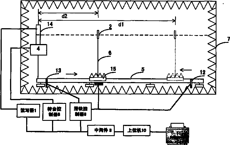
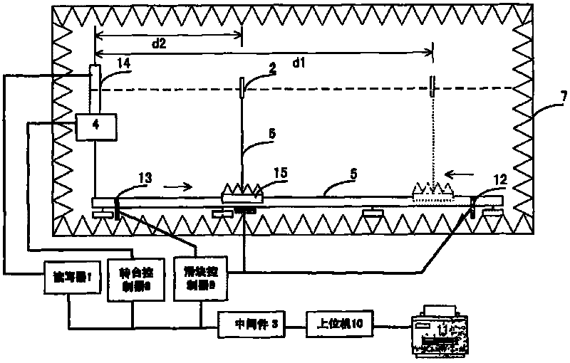
[0044] like figure 1Shown is the structural diagram of the power line measurement system of the reader-writer antenna of the present invention, in which it is shown: reader-writer 1, electronic tag 2, middleware 3, turntable 4, horizontal guide rail 5, support 6, microwave anechoic chamber 7, turntable Controller 8, slider controller 9, upper computer 10, drawing and printing device 11, two positioning sensors 12, 13, reader antenna 14 and slider 15. The reader antenna 14 is placed on the turntable 4 and can run synchronously with the turntable 4, and the turntable 4 stands on the ground of the darkroom through supports. The test electronic tag 2 is fixed on the bracket 6, and the material of the bracket 6 is wood or pla...


PUM


Abstract

The invention discloses a measuring system and a measuring method for a power contour of a reader-writer antenna. The measuring system comprises a reader-writer arranged outside a microwave dark room, middleware, a rotary table controller, a sliding block controller, a host computer and a drawing printer, wherein an electronic tag, a rotary table, a horizontal guide rail, a bracket, two positioning sensors, the reader-writer antenna and a sliding block are arranged in the microwave dark room. The method reflects a reader-writer response electronic tag zone to a certain degree by measuring feedback points with the same power in a three-dimensional direction of the reader-writer antenna, so the method has deeper realistic meaning than a directional diagram. An electromechanical device ensures automatic performance of the measuring method, a testing environment provides free space and a test result becomes more persuasive and reliable. The measuring system and the measuring method have a reference value for the field application of a wireless radiofrequency recognition system and the layout of a tag.

Description

technical field [0001] The invention belongs to the technical field of electronic information, and mainly relates to an automatic measurement system and a measurement method for a radio frequency identification (RFID) system. Background technique [0002] Antenna pattern measurement has long been a focus of wireless device testing. For radio frequency identification systems, especially for UHF and microwave frequency bands, the test of the directional pattern of the reader antenna is more intuitive. [0003] Based on the technical principle of the radio frequency identification system, the information exchange between the reader and the electronic tag forms a one-to-many linear mode, so there will be a problem in the test process: in what range the electronic tag can be read and written by the device Responding to, within which range the electronic tag cannot be responded to? The dividing line formed by the response area and the non-response area has a very realistic guidi...

Claims


Application Information

Patent Timeline
Patent Type & Authority Applications(China)
IPC IPC(8): G01R29/10
Inventor 王宏伟谭杰郁文生朱智源
Owner INST OF AUTOMATION CHINESE ACAD OF SCI
Why Eureka
Try Eureka