
Isolation switch and switch cabinet with same

A technology of isolating switch and static contact, which is applied in the field of switchgear, can solve problems such as unreliability, potential safety hazards of switchgear, and inability to guarantee contact reliability of isolating switches, so as to prolong service life, reduce potential safety hazards, and avoid poor contact Effect

Active Publication Date: 2012-10-10
BEIJING CREATIVE DISTRIBUTION AUTOMATION
View PDF1 Cites 0 Cited by
  • Summary
  • Abstract
  • Description
  • Claims
  • Application Information

AI Technical Summary

Problems solved by technology

[0005] However, the isolating switch has the following disadvantages: the clamping of the contact knife and the contact is completed at the same time during the closing process. If the clamping force of the contact knife is large, it will be very difficult to complete the closing and opening by hand; in order to be able to manually operate , by reducing the clamping force of the contact knife, if the clamping force is small, the ability of the isolating switch to resist the electric force will inevitably decrease and become worse, and at the same time the contact pressure of the isolating switch will also decrease, and the contact reliability of the isolating switch cannot be guaranteed. There are potential safety hazards during operation (unreliable contact will cause the temperature rise of the contact point to rise, causing thermal breakdown of the insulation, destroying the insulation of the isolating switch, and causing insulation accidents)
[0009] The structures of the above two patent solutions are all spring clamping solutions. After long-term use, it will lead to serious wear of the contacts and contacts, and will also lead to a decrease in the elastic force, which will reduce the closing pressure of the contacts and the closure will not be tight.
As a result, the temperature rise at the contact is mentioned, and the spring is aging, which brings safety hazards to the use of the switchgear

Method used


Image

  • Isolation switch and switch cabinet with same
  • Isolation switch and switch cabinet with same
  • Isolation switch and switch cabinet with same

Examples


Embodiment Construction

[0051] Below in conjunction with accompanying drawing, the present invention is described in further detail:

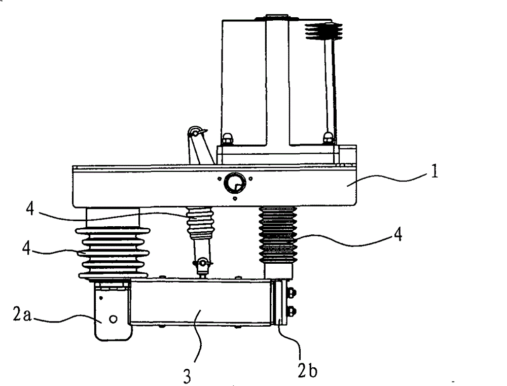
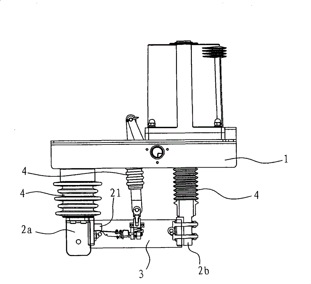
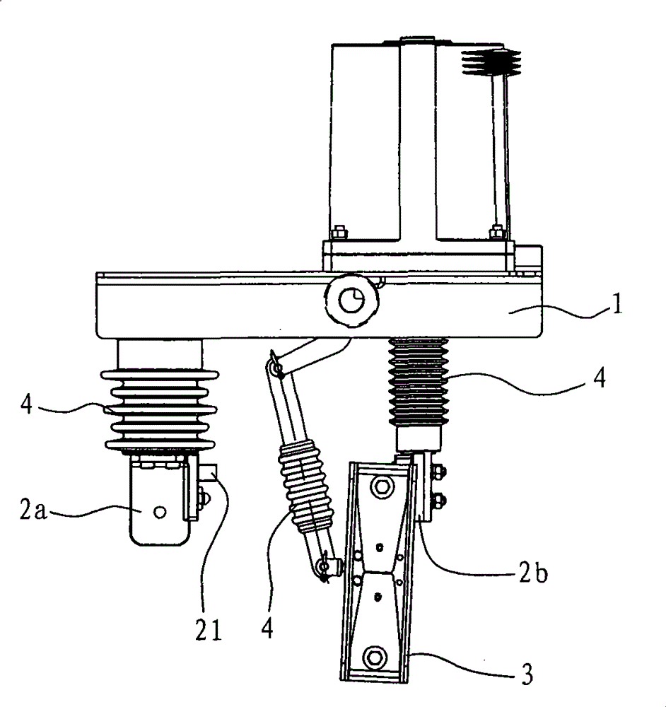
[0052] Such as Figure 1 to Figure 9 As shown, a isolating switch provided by the present invention includes a bracket 1, a static contact, and a movable contact blade assembly 3 respectively matched with the static contacts. The movable contact blade assembly 3 and the static contact are respectively connected with an insulator 4, The insulator 4 is installed on the bracket 1, the movable contact knife assembly 3 includes a clamping part, and the clamping part has a clamping space 5 matched with the static contact; The clamping mechanism and the driving part 6 that drives the action of the clamping mechanism; the moving contact knife assembly 3 also includes a mechanical position sensing mechanism that the driving part 6 can only move when the static contact enters the predetermined position of the clamping space 5, The mechanical position sensing mechanism includes...


PUM


Abstract

The invention relates to an isolation switch. The isolation switch comprises a bracket, a fixed contact, a movable contact knife component and an insulator, wherein the movable contact knife component comprises a clamping part; the clamping part is provided with a clamping space, a clamping mechanism, a driving part and a mechanical position sensing mechanism; the mechanical position sensing mechanism comprises a position sensing end and an action triggering end; and the position sensing end is in fit with the fixed contact, while the action triggering end is in fit with the driving part. In the isolation switch, the clamping mechanism, the driving part and the mechanical position sensing mechanism are in fit connection, and the functions that the contact is switched on and then is lockedand that the fixed contact is unlocked and then is switched off after the movable contact knife component moves to a position where the movable contact knife component can be closed with the fixed contact; in the whole switching-in and switching-off process, the contact is not abraded and has long service life, the closing pressure of the contact is great, through-current capacity is strong, a disconnecting link is not easy to heat and potential safety hazard is reduced; and simultaneously, in the whole process, closing and locking conversion operations have clear gears and easy conversion and are convenient and smooth to execute.

Description

technical field [0001] The invention relates to an isolating switch applied in power system equipment. The invention also relates to a switchgear fitted with the isolating switch. Background technique [0002] Isolating switch plays an important role in isolating power supply, changing system operation mode and switching operation in power system. [0003] Among the technical requirements of the isolating switch, the most important point is how to better solve the problems of contact wear and contact pressure when the isolating switch is closed and disconnected, and how to prolong the service life of the contacts. In addition, it is also necessary to consider whether the operation of the isolating switch when closing and disconnecting is labor-saving, smooth and convenient. [0004] At present, the clamping method of the isolating switch basically adopts the structural scheme of clamping springs. This type of isolating switch is an indoor knife-type three-pole isolating s...

Claims


Application Information

Patent Timeline
Patent Type & Authority Patents(China)
IPC IPC(8): H01H31/30H01H1/36H02B1/00H02B1/04
Inventor 胡兆明刘大祥张薇彤叶祖标李占生阿进福
Owner BEIJING CREATIVE DISTRIBUTION AUTOMATION
Learn More