
Circuit oscillator for clock signal generation and control

An oscillating device, a clock signal technology, applied in the direction of generating electric pulses, pulse generation, automatic power control, etc., can solve the problems of high power consumption, high cost of phase-locked loop IP, complex structure, etc. Reusable, simple-structured effects

Active Publication Date: 2012-02-01
SHENYANG INST OF AUTOMATION - CHINESE ACAD OF SCI
View PDF0 Cites 0 Cited by
  • Summary
  • Abstract
  • Description
  • Claims
  • Application Information

AI Technical Summary

Problems solved by technology

Now almost all digital circuits are designed with sequential circuits. The clock (CLOCK) is an essential signal in all sequential circuits. The clocks of most digital circuits are directly input from the outside or embedded in the circuit. Phase-locked loop (PLL) IP However, the phase-locked loop IP has disadvantages such as high cost, complex structure, and high power consumption.

Method used


Image

  • Circuit oscillator for clock signal generation and control
  • Circuit oscillator for clock signal generation and control
  • Circuit oscillator for clock signal generation and control

Examples


Embodiment

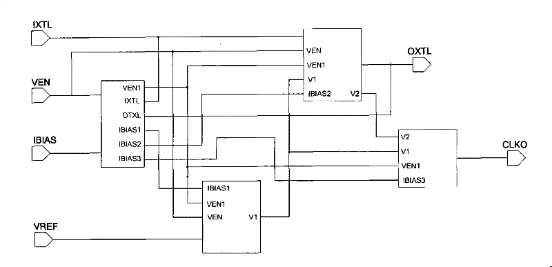
[0018] Such as figure 1 As shown, a circuit oscillation device for clock signal generation and control, the device takes the control and bias circuit module as the core, its signal output terminal is connected with a reference generation circuit module; its signal output terminal is also connected with an oscillation generation circuit module and a clock output circuit module; the output end of the reference generation circuit module is also connected with an oscillation generation circuit module and a clock output circuit module.

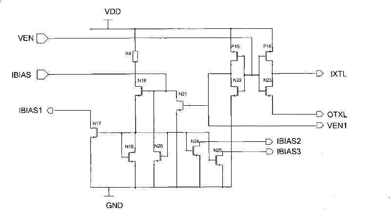
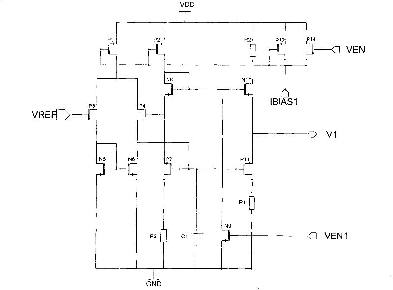
[0019] The control and bias circuit module receives the first enable control signal (VEN) and the first bias current signal (IBIAS); the control and bias circuit module outputs the second enable control signal (VEN1) and the second bias current signal The current signal (IBIAS1) is sent to the reference generation circuit module; it outputs the second enable control signal (VEN1) and the third bias current signal (IBIAS2) to the oscillation generat...


PUM


Abstract

The invention discloses a circuit oscillation device for clock signal generation and control. The device takes a control and bias circuit module as the core, and its signal output terminal is connected with a reference generation circuit module; its signal output end is also connected with an oscillation generation circuit module and a clock output circuit module; the output of the reference generation circuit module is also connected to an oscillation generation circuit module and a clock output circuit module; a modular design is adopted, which has a simple structure, low power consumption, and reusability, and can be used in the chip Internally integrated, it can generate and control the clock signal, and it also has the advantages of cost saving, improved circuit integration, stability and reliability; the oscillator circuit can generate 460.8kHz clock, support chip selection effective function, and can support external clock directly Input and / or use an externally connected crystal to generate a clock with the advantage of two modes of operation.

Description

technical field [0001] The invention relates to the technical field of integrated circuit design, in particular to a circuit oscillation device for clock signal generation and control. Background technique [0002] In recent years, with the rapid development of the domestic integrated circuit industry, the technological level of integrated circuit production has been continuously improved, and IC design technology has been continuously innovated. . At present, the design of digital-analog hybrid integrated circuits has become a difficult point and a hot spot in the integrated circuit design industry. Now almost all digital circuits are designed with sequential circuits. The clock (CLOCK) is an essential signal in all sequential circuits. The clocks of most digital circuits are directly input from the outside or embedded in the circuit. Phase-locked loop (PLL) IP However, the phase-locked loop IP has disadvantages such as high cost, complex structure, and high power consump...

Claims


Application Information

Patent Timeline
Patent Type & Authority Patents(China)
IPC IPC(8): H03K3/012H03L7/06H03L7/099G06F1/04
Inventor 刘铁锋王建军吕岩金硕巍段茂强刘志峰
Owner SHENYANG INST OF AUTOMATION - CHINESE ACAD OF SCI
Learn More