
Slot antenna and method for RFID

A technology for slot antennas and antennas, which is applied in the direction of slot antennas, antennas, antenna arrays, etc., can solve the problems of unsuitable high space requirements, and achieve the effects of compact structure, reduced size, and shortened wavelength

Inactive Publication Date: 2015-04-01
PEPPERL FUCHS GMBH
View PDF6 Cites 0 Cited by
  • Summary
  • Abstract
  • Description
  • Claims
  • Application Information

AI Technical Summary

Problems solved by technology

However, when the lowest sensitivity in known systems is required, the gain produced by the antenna must remain the same, which does not seem to be achievable with hitherto known antennas
[0011] Besides slot antennas, other antenna types are either unknown or unsuitable due to their high space requirements

Method used


Image

  • Slot antenna and method for RFID
  • Slot antenna and method for RFID
  • Slot antenna and method for RFID

Examples


Embodiment Construction

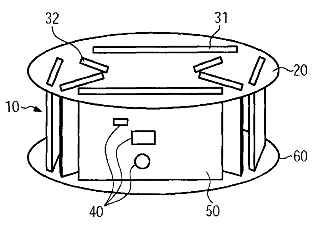
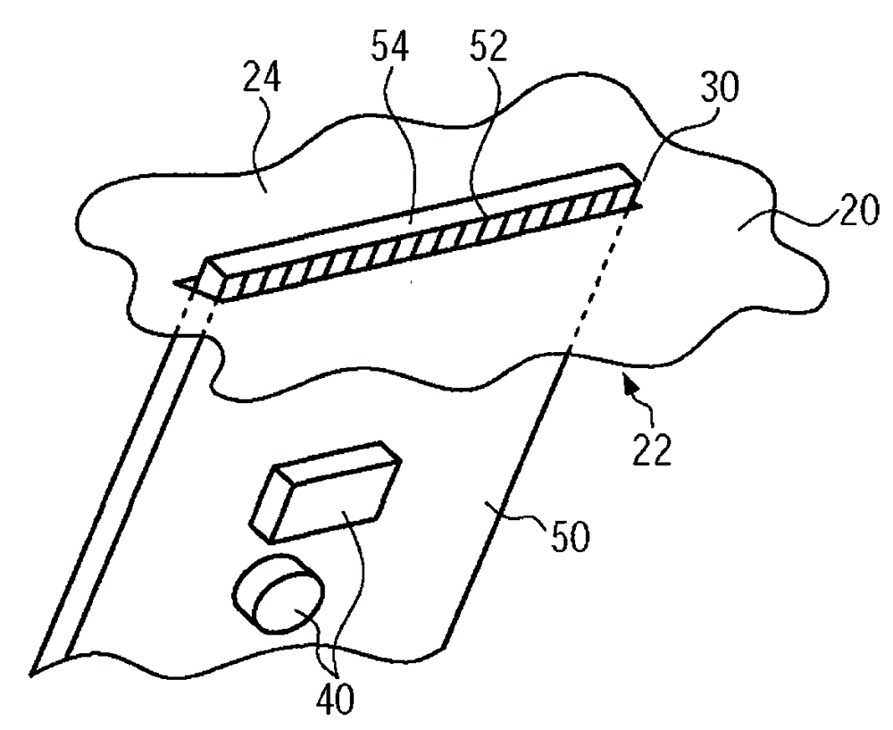
[0045] Reference Figure 1 to Figure 3 An exemplary embodiment of the antenna 10 of the present invention will be described. The same parts are given the same reference signs.

[0046] The antenna 10 of the present invention includes an antenna contour board (antenna contour board) 20 as its main components, a plurality of circuit boards 50 having a control circuit 40 disposed thereon, and a stabilizer board 60 that can also carry electronic components.

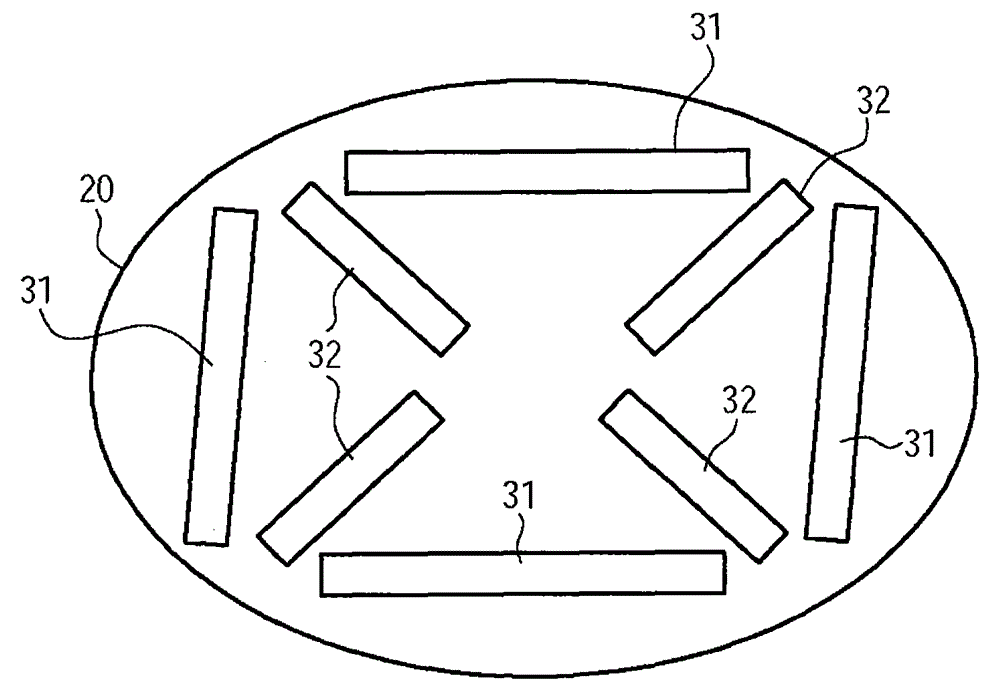
[0047] figure 2 The antenna profile plate 20 shown in FIG. 2 includes two antenna systems positioned orthogonal to each other. The first antenna system includes a rectangular array of four antenna slots 31, and the second slot system includes four antenna slots 32 arranged in a crossed arrangement. The antenna slots 32 arranged in a cross arrangement are positioned within the rectangle formed by the antenna slots 31 and are approximately aligned on the diagonal of the latter.

[0048] Therefore, the gap systems are nested with e...


PUM


Abstract

The invention relates to a slot antenna, more particularly to a transmitting antenna for RFID, comprising an antenna contour board having a plurality of antenna slots and at least one control circuit for enabling the antenna contour board to transmit and / or receive electromagnetic radiation. The slot antenna is characterized in that in at least one antenna slot of the antenna contour board there is inserted a circuit board carrying a control circuit. The invention further relates to an RFID method involving the use of the slot antenna of the invention.

Description

Technical field [0001] The present invention relates in a first aspect to a slot antenna, and more particularly to a transmitting antenna for RFID according to the preamble of claim 1. [0002] In another aspect, the invention relates to an RFID method. Background technique [0003] A general type of slot antenna includes at least one antenna profile with multiple antenna slots, and at least one control circuit for causing the antenna profile to emit and / or receive electromagnetic radiation. [0004] The technology used to remotely identify objects and people through radio waves (Radio Frequency Identification RFID) is used in many different fields. [0005] For example, RFID technology is used in military applications, identification cards, libraries, and especially industrial manufacturing and automation. [0006] The ever-increasing number of closely-stacked electrical and electronic devices is causing more and more industrial environmental problems. In this case, the problem to be...

Claims


Application Information

Patent Timeline
Patent Type & Authority Patents(China)
IPC IPC(8): H01Q13/10H01Q1/22H01Q23/00H01Q3/36H01Q21/24
CPCH01Q1/2216H01Q13/10H01Q23/00H01Q3/36H01Q21/245
Inventor 斯蒂芬·阿尔布里施特
Owner PEPPERL FUCHS GMBH
Learn More