Mine anti-explosion diesel engine railless free-wheeled vehicle front axle suspension system

An explosion-proof technology for trackless rubber-tyred vehicles and mines, which is applied to locomotives, suspensions, vehicle components, etc., and can solve bumps, front axle splints, spring breakage of connecting bolts, reliability, service life, stability, passability, etc. The index requirements are particularly harsh and other issues, to achieve the effect of avoiding hard collision, good shock absorption effect and reasonable force

Inactive Publication Date: 2010-06-30
昆山晋桦豹胶轮车制造股份有限公司
View PDF0 Cites 3 Cited by
  • Summary
  • Abstract
  • Description
  • Claims
  • Application Information

AI Technical Summary

Problems solved by technology

[0002] Mining explosion-proof diesel engine trackless rubber-tyred vehicles are used in the transportation of personnel and materials in large coal mines. Due to the harsh working conditions in coal mines, the reliability of each component of the rubber-tyred vehicle is strictly required, and the reliability and service life of the suspension mode of the rubber-tyred vehicle axle , stability, passability and other indicators are particularly demanding. At present, the front axle suspension device of the existing technology of various domestic explosion-proof diesel engine trackless rubber-tyred vehicles generally adopts the structure of rigid connection between the drive axle and the frame. The results of use show that when the rubber-tyred vehicle is running, because the chassis of the rubber-tyred vehicle cannot adapt to the undulations of the underground ground in the coal mine, it causes a lot of bumps, and there are cracks in the front axle splint, connecting bolts, springs, etc.

Method used


Image

  • Mine anti-explosion diesel engine railless free-wheeled vehicle front axle suspension system
  • Mine anti-explosion diesel engine railless free-wheeled vehicle front axle suspension system
  • Mine anti-explosion diesel engine railless free-wheeled vehicle front axle suspension system

Examples


Embodiment Construction

[0014] Hereinafter, the present invention will be described in detail with reference to the accompanying drawings.

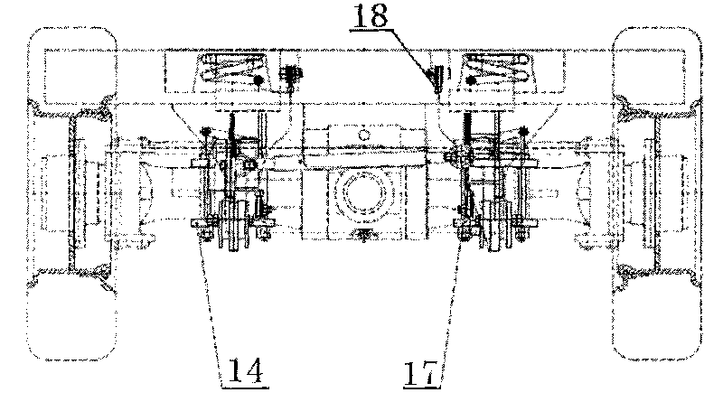
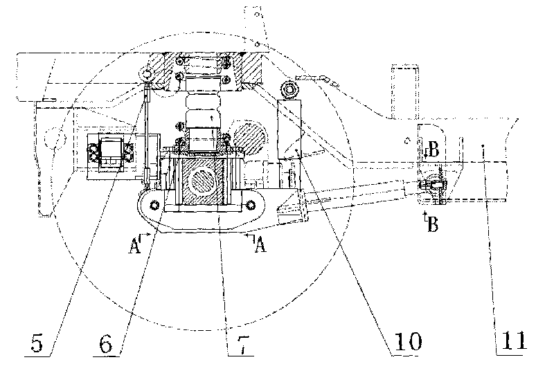
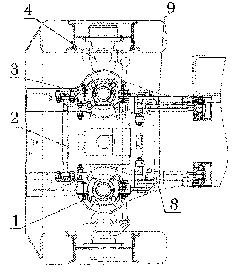
[0015] Such as figure 1 , figure 2 and image 3 As shown, according to the mine explosion-proof diesel engine trackless rubber-tyred vehicle front axle suspension device in the present invention, comprises the following several parts: left spring support 1, front axle tie rod 2, right spring support 3, front axle 4, front Bridge wire rope 5, front pressure spring 6, front damping rubber 7, left push rod 8, right push rod 9, shock absorber 10, vehicle frame 11, limit sleeve 12, push rod rubber block 13, right splint 14, block Ring 15, shaft 16, left splint 17, sleeve 18,

[0016] The front axle 4 is installed on the left push rod 8 and the right push rod 9 hinged with the vehicle frame 11 at one end, the left push rod 8 and the right push rod 9 are hinged with the vehicle frame 11 through the shaft 16, and the outside of the shaft 16 is provided with a retain...


PUM


Abstract

The invention relates to a mine anti-explosion diesel engine railless free-wheeled vehicle front axle suspension system. The front axle is arranged on a left push rod and a right push rod one end of which are hinged with frame, the left push rod and the right push rod are respectively provided with a left spring support and a right spring support, the left spring support and the right spring support are respectively provided with a front pressure spring and a front damping rubber, and meanwhile the front axle is also connected with the frame by two front axle steel wire ropes and two damping devices which are connected thereon; wherein the hinged position of the frame and the front axle is provided with a front axle tierod, and a rubber hinge is adopted at the hinged position between the two ends of the front axle as well as the frame and the front axle. The hinged position of the left push rod and right push rod as well as the frame adopts a rubber hinge. The hinged position of the left push rod and right push rod as well as the front axle adopts a polyurethane elastic hinge. The invention avoids collision between parts, stress is more scientific, damping effect is better; the stress of the damping spring is more reasonable, and the service life of front axle splint, connecting bolt and spring is improved.

Description

technical field [0001] The invention relates to the manufacture of underground vehicles in coal mines, and in more detail relates to a front axle suspension device for mine explosion-proof diesel engine trackless rubber-tyred vehicles. Background technique [0002] Mining explosion-proof diesel engine trackless rubber-tyred vehicles are used in the transportation of personnel and materials in large coal mines. Due to the harsh working conditions in coal mines, the reliability of each component of the rubber-tyred vehicle is strictly required, and the reliability and service life of the suspension mode of the rubber-tyred vehicle axle , stability, passability and other indicators are particularly demanding. At present, the front axle suspension device of the existing technology of various domestic explosion-proof diesel engine trackless rubber-tyred vehicles generally adopts the structure of rigid connection between the drive axle and the frame. The results of use show that w...

Claims


Application Information

Patent Timeline
IPC IPC(8): B60G21/04B60G21/055B61C13/00
Inventor 黎明韦保新金柳凯
Owner 昆山晋桦豹胶轮车制造股份有限公司
Why Eureka
Try Eureka