Crane beam frame construction method

A construction method and crane beam technology, applied in the directions of load hanging components, transportation and packaging, support structures, etc., can solve the problems of low safety and low working efficiency at high altitudes, and achieve good results and reduce the risk of falling objects. possible, the effect of promoting construction quality

Active Publication Date: 2010-06-30
MCC5 GROUP CORP SHANGHAI
View PDF0 Cites 11 Cited by
  • Summary
  • Abstract
  • Description
  • Claims
  • Application Information

AI Technical Summary

Problems solved by technology

This will inevitably make the operator install each single component at a high place. This construction method has a low degree of safety and low efficiency for high-altitude operations.

Method used


Image

  • Crane beam frame construction method
  • Crane beam frame construction method
  • Crane beam frame construction method

Examples


Embodiment 1

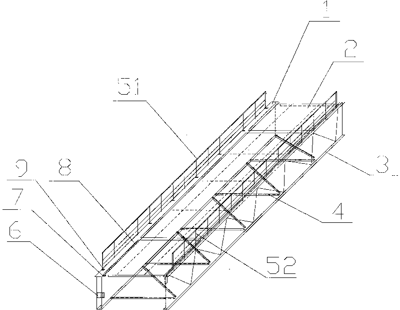
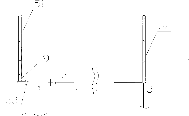
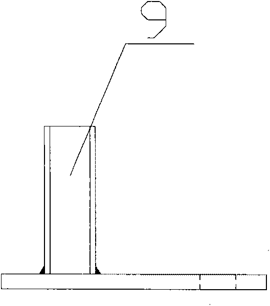
[0017] Now it is necessary to carry out the construction of the crane beam frame in a cold rolling workshop. The whole construction is divided into three steps: ground assembly, overall hoisting, and the use of formal railings. The crane beam frame consists of crane beam 1, brake plate 2, truss 3, and horizontal support frame 4 , temporary railing 51, formal railing 52, railing bolt 53, connecting plate 6, hinge plate 7, brake plate bolt 8 and connecting member 9, as figure 1 and figure 2 As shown, the crane beam 1 and the auxiliary truss 3 are arranged parallel to each other, the upper part of the crane beam 1 is fixedly connected with the brake plate 2 through the brake plate bolt 8, and the upper part of the auxiliary truss 3 is fixedly connected with the brake plate 2 by welding. 1 and the lower part of the auxiliary truss 3 are fixedly connected through the horizontal support frame 4, and the cross section of the crane beam 1 is fixed with a connecting plate 6, and the a...


PUM


Abstract

The invention relates to the crane beam system construction field, in particular to a crane beam frame construction method. The method comprises three steps of assembling on the ground, integral-hoisting and commissioning of formal railings. The crane beam frame comprises a crane beam (1), a brake board (2), a truss (3), a horizontal support frame (4), a connection plate (6), a hinge plate (7) and stopping plate bolts (8). The crane beam frame is characterized in that the crane beam frame also comprises temporary railings (51), formal railings (52), railing bolts (53) and connection members (9), the upper part of the crane beam (1) is fixed with the temporary railings (51) through the connection members (9) and the railing bolts (53), the upper part of the auxiliary truss (3) is welded and fixed with the formal railings (52); and the integral-hoisting and the commissioning of the formal railings are performed in turn after the crane beam frame is assembled on the ground. The invention reduces the quantity of works at heights, the operation is safe, the working efficiency and quality are high, the investment is little and the applicability is high.

Description

technical field [0001] The invention relates to the field of crane beam system construction, in particular to a crane beam frame construction method. Background technique [0002] In the construction of modern large-scale industrial plants, the crane beam system of steel structure is widely used. The installation position of the crane beam system is high, and there are many system components. For example, there are 148 crane girder systems in a steel factory, with a total weight of 2240 tons, 32 components per crane girder system, and an installation elevation of +15m. At present, the commonly used installation method is to hoist a single piece to a high place and connect it into a system. This will inevitably make the operator install each single component at a high place, the safety of this construction method is low, and the efficiency of high place operation is also low. Contents of the invention [0003] In order to ensure the safety of operators when installing a ...

Claims


Application Information

Patent Timeline
Patent Type & Authority Applications(China)
IPC IPC(8): B66C6/00
Inventor 陈广忠陈贻王祥
Owner MCC5 GROUP CORP SHANGHAI
Why Eureka
Try Eureka