Fiber reinforced concrete uplift pile

A technology of concrete piles and fiber reinforcement, which is applied in sheet pile walls, buildings, infrastructure engineering, etc., can solve the problem that the bonding performance of FRP fibers and concrete is not very mature.

Inactive Publication Date: 2010-06-30
NANCHANG CONSTR ENG GROUP
View PDF0 Cites 18 Cited by
  • Summary
  • Abstract
  • Description
  • Claims
  • Application Information

AI Technical Summary

Problems solved by technology

Different types of FRP tendons have different properties, but as new composite materials used in civil engineering, there are many commonalities between them: high tensile strength along the fiber direction; low density, light weight, easy construction; corrosion resistance; Excellent fatigue performance, etc., but the bonding performance between FRP fiber and concrete is not very mature

Method used


Image

  • Fiber reinforced concrete uplift pile
  • Fiber reinforced concrete uplift pile
  • Fiber reinforced concrete uplift pile

Examples


Embodiment 1

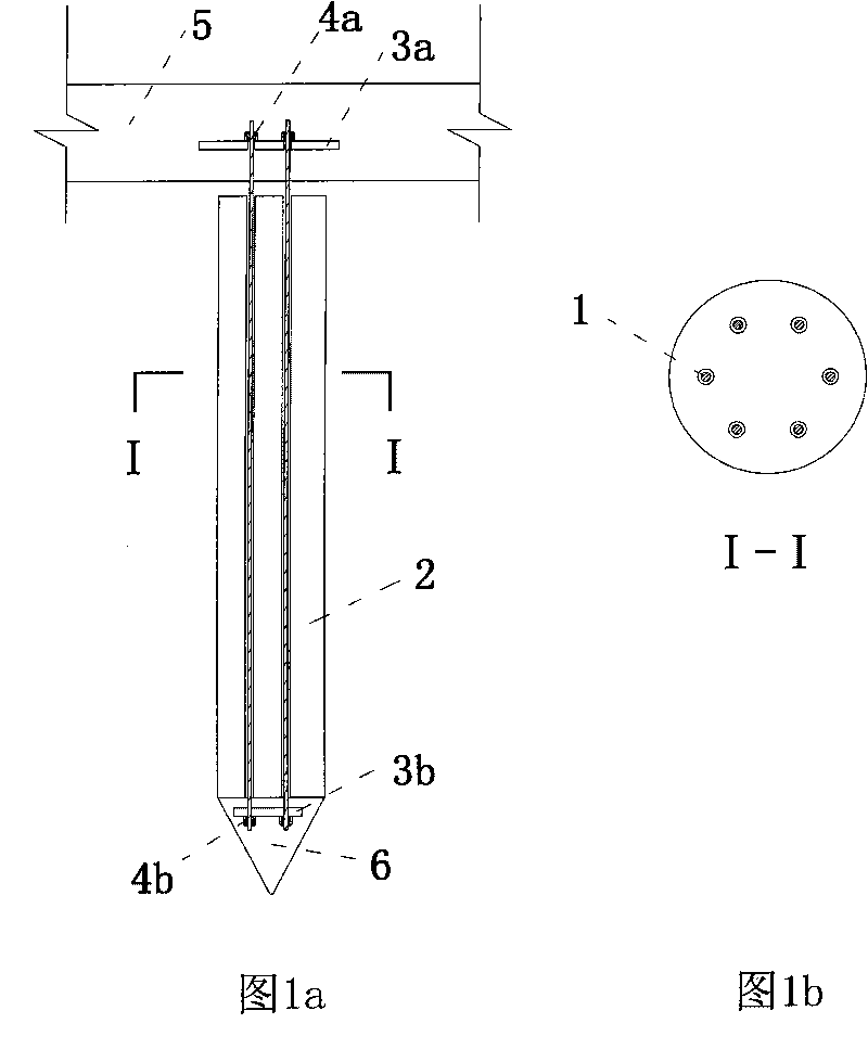
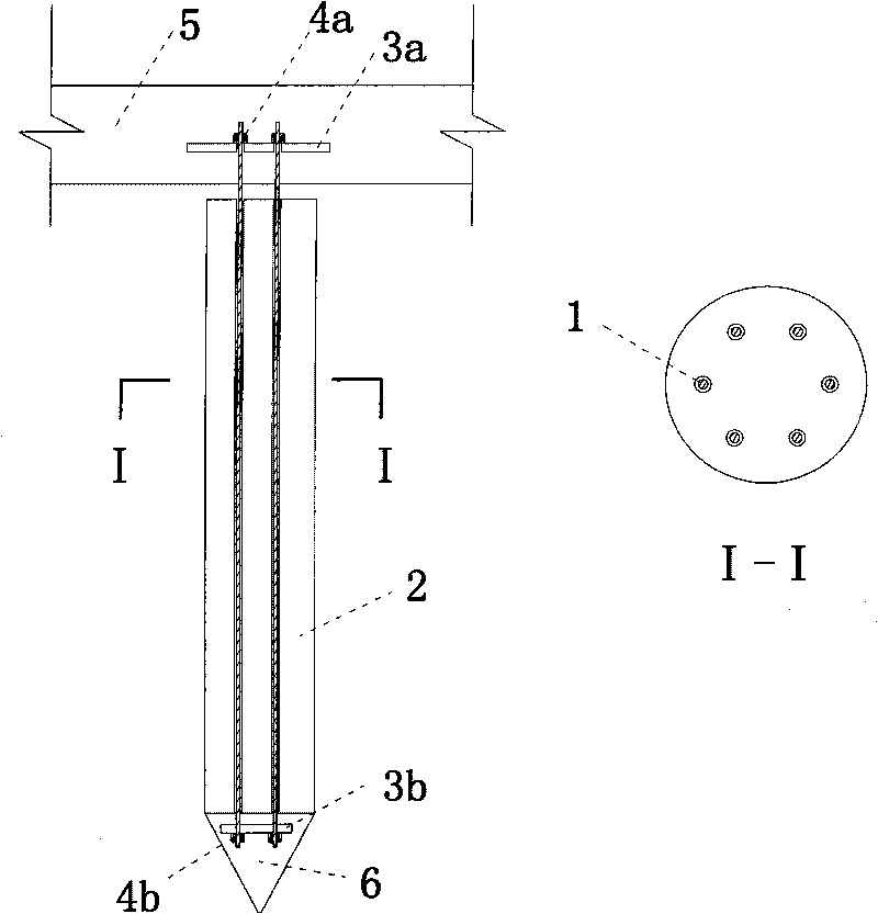
[0016] A fiber-reinforced concrete uplift pile, comprising: a concrete pile body 2, a pile head 6 is arranged on one end of the concrete pile body 2, and an FRP fiber reinforcement 1 with an external sleeve sleeve is arranged inside the concrete pile body 2 And one end of the FRP fiber reinforcement 1 extends into the pile head 6, and the other end of the FRP fiber reinforcement 1 extends out of the concrete pile body 2 in reverse; a second support plate 3b is provided in the pile head 6, located at One end of the FRP fiber reinforcement 1 in the pile head 6 is fixed on the second support plate 3b by the second anchor 4b; the first support plate 3a is sleeved on the other end of the FRP fiber reinforcement 1, and the FRP fiber reinforcement 1 is supported by the first anchor 4a. The other end of the fiber tendon 1 is fixed on the first support plate 3a.

[0017] Such as figure 1 , consisting of FRP fiber reinforcement 1 with casing, concrete pile body 2, first support plate 3...

Embodiment 2

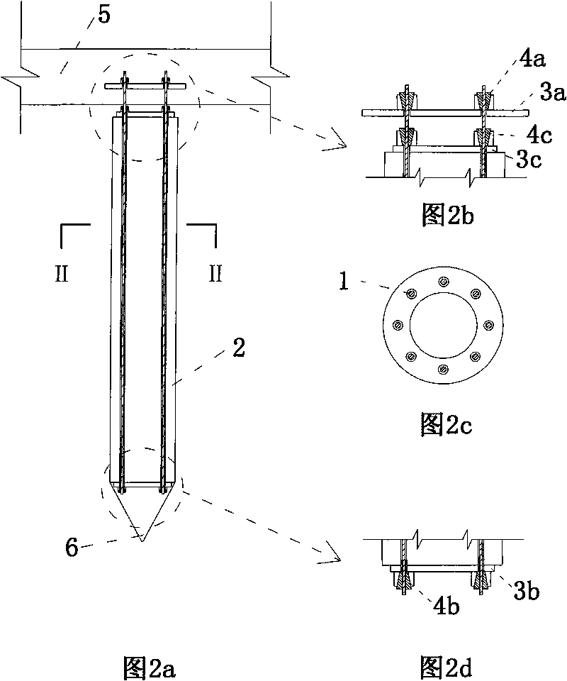
[0019] A fiber-reinforced concrete uplift pile, comprising: a concrete pile body 2, a pile head 6 is arranged on one end of the concrete pile body 2, and an FRP fiber reinforcement 1 with an external sleeve sleeve is arranged inside the concrete pile body 2 And one end of the FRP fiber reinforcement 1 extends into the pile head 6, and the other end of the FRP fiber reinforcement 1 extends out of the concrete pile body 2 in reverse; a second support plate 3b is provided in the pile head 6, located at One end of the FRP fiber reinforcement 1 in the pile head 6 is fixed on the second support plate 3b by the second anchor 4b; the first support plate 3a is sleeved on the other end of the FRP fiber reinforcement 1, and the FRP fiber reinforcement 1 is supported by the first anchor 4a. The other end of the fiber reinforcement 1 is fixed on the first support plate 3a. In this embodiment, the other end of the FRP fiber reinforcement 1 is also sleeved with a third support plate 3c, and t...


PUM


Abstract

The invention relates to a fiber reinforced concrete uplift pile which comprises a concrete pile body. A pile head is arranged at one end part of the concrete pile body; a FRP fiber reinforcement externally sleeved by a sleeve is arranged in the concrete pile body, one end thereof extends into the pile head, and the other end thereof reversely extends out of the concrete pile body; a second supporting plate is arranged in the pile head; one end of the FRP fiber reinforcement positioned in the pile head is fixed on a second supporting plate by a second anchorage device; a first supporting plate is sleeved at the other end of the FRP fiber reinforcement, and the other end of the FRP fiber reinforcement is fixed on the first supporting plate by a first anchorage device. Prestressing force is not applied to the FRP fiber reinforcement, the sleeve is enwrapped on the periphery of the FRP fiber reinforcement and is not bonded with concrete; and relative slide can be generated between the sleeve and the concrete. The lower end of the FRP fiber reinforcement is tensioned by the supporting plates at the bottom part of the pile and the anchorage devices, and the upper end of the RP fiber reinforcement is fixed in a bearing platform by the supporting plates in the bearing platform and the anchorage devices; and the bearing platform is completely separated with the concrete of the pile body.

Description

technical field [0001] This patent relates to a fiber-reinforced concrete uplift pile. Background technique [0002] With the rapid development of the economy, the urban space is becoming increasingly scarce, which has triggered an upsurge in the development of underground space. The safe use of various underground projects is without exception affected by the buoyancy of groundwater. Therefore, the uplift pile has been more and more widely used in the project. application. The uplift piles are located underground, surrounded by soil and groundwater. In order to prevent the erosion of steel bars by groundwater and chemical substances, the design code has strict requirements on the crack control of the uplift piles. At present, the uplift pile generally adopts two forms of concrete pouring pile and concrete prefabricated pile, and the reinforcement ratio of the section is controlled by the crack resistance requirement. According to the provisions of the "Technical Specifica...

Claims


Application Information

Patent Timeline
Patent Type & Authority Applications(China)
IPC IPC(8): E02D27/12E02D5/22E02D5/52
Inventor 梅国雄周峰张乾宋林辉梅岭
Owner NANCHANG CONSTR ENG GROUP
Why Eureka
Try Eureka