Steel column and beam structure with corrugated steel web and special welding device thereof

A corrugated steel web and welding device technology, applied in auxiliary devices, welding equipment, truss structures, etc., can solve the problems of poor anti-overturning performance, easy torsion of I-beam steel beams, low compressive strength, etc., to achieve Strong anti-seismic performance, saving steel and light weight

Inactive Publication Date: 2010-06-30
ZHEJIANG CTB WAVEFORM STEEL WEB
View PDF1 Cites 24 Cited by
  • Summary
  • Abstract
  • Description
  • Claims
  • Application Information

AI Technical Summary

Problems solved by technology

[0003] The present invention aims at the disadvantages of low compressive strength and poor anti-overturning performance of I-beams whose webs are ordinary steel plates in the prior art, and the I-beam beams are easily toppled when subjected to radial force, etc., and provides an intermediate web

Method used


Image

  • Steel column and beam structure with corrugated steel web and special welding device thereof
  • Steel column and beam structure with corrugated steel web and special welding device thereof
  • Steel column and beam structure with corrugated steel web and special welding device thereof

Examples


Embodiment 1

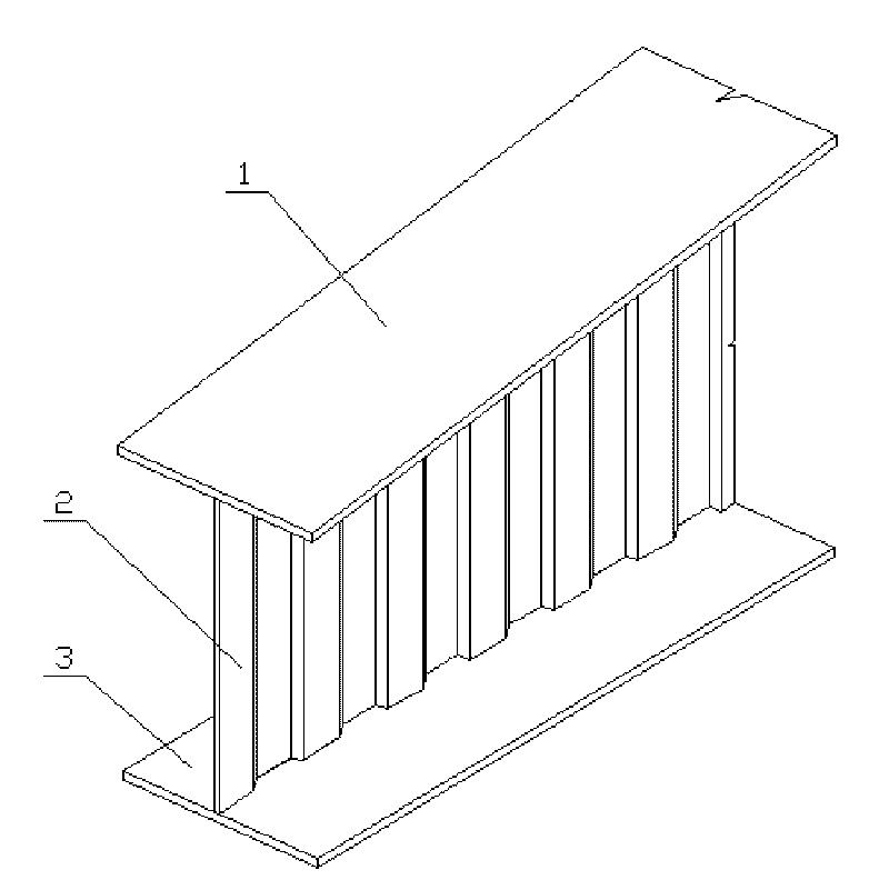
[0028] Corrugated steel web steel column steel beam structure and special welding devices, such as figure 1 , 2 , 7, 8, and 9, including an upper wing 1, a lower wing 3, and a web 2 arranged between the upper wing 1 and the lower wing 3, the upper wing 1 and the lower wing 3 is a plate with a thickness of 5mm, and the web 2 is a corrugated steel web with a thickness of 5mm. 1. The section of the lower wing 3 and the web 2 is "I" shape, the web 2 and the upper wing 1 are connected by welding, and the web 2 and the lower wing 3 are connected by welding. Corrugated steel web The web between the upper flange and the lower flange of the steel column steel beam adopts corrugated steel web, so under the premise of satisfying the same structural strength and mechanical properties, the I-beam with corrugated steel web is also better than the ordinary I-beam The beam saves more steel, and has an anti-twist effect that cannot be compared with ordinary I-shaped beams.

[0029] The uppe...

Embodiment 2

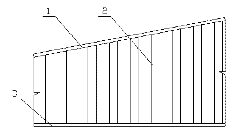
[0036] Corrugated steel web steel column steel beam structure and special welding devices, such as image 3 , 4, 7, 8, and 9, including an upper wing 1, a lower wing 3, and a web 2 arranged between the upper wing 1 and the lower wing 3, the upper wing 1 and the lower wing 3 is a plate with a thickness of 10mm, web 2 is a corrugated steel web with a thickness of 6mm, and the surfaces of upper flange 1, lower flange 3 and web 2 are prepared with a roughness of 120μm; 1. The section of the lower wing 3 and the web 2 is "I" shape, the web 2 and the upper wing 1 are connected by welding, and the web 2 and the lower wing 3 are connected by welding. Corrugated steel web The web between the upper flange and the lower flange of the steel column steel beam adopts corrugated steel web, so under the premise of satisfying the same structural strength and mechanical properties, the I-beam with corrugated steel web is also better than the ordinary I-beam The beam saves more steel, and has ...

Embodiment 3

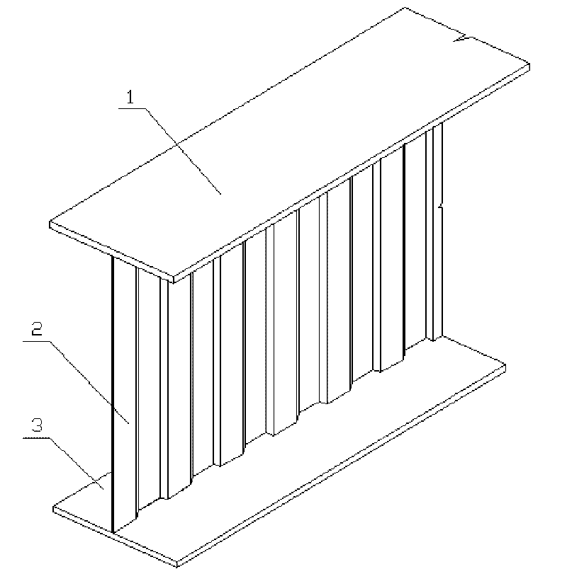
[0044] Corrugated steel web steel column steel beam structure and special welding devices, such as Figure 5 , 6 , 7, 8, and 9, including an upper wing 1, a lower wing 3, and a web 2 arranged between the upper wing 1 and the lower wing 3, the upper wing 1 and the lower wing 3 is a plate with a thickness of 20mm, web 2 is a corrugated steel web with a thickness of 8mm, and the surfaces of upper flange 1, lower flange 3 and web 2 are prepared with a roughness of 200μm; 1. The section of the lower wing 3 and the web 2 is "I" shape, the web 2 and the upper wing 1 are connected by welding, and the web 2 and the lower wing 3 are connected by welding. Corrugated steel web The web between the upper flange and the lower flange of the steel column steel beam adopts corrugated steel web, so under the premise of satisfying the same structural strength and mechanical properties, the I-beam with corrugated steel web is also better than the ordinary I-beam The beam saves more steel, and ha...


PUM

PropertyMeasurementUnit
Thicknessaaaaaaaaaa
Thicknessaaaaaaaaaa
Thicknessaaaaaaaaaa

Abstract

The invention relates to a steel column and beam structure used in the building and a welding device thereof, particularly discloses a steel column and beam structure with a corrugated steel web and a special welding device thereof. The steel column and beam structure comprises an upper wing plate, a lower wing plate and a web plate arranged between the upper wing plate and the lower wing plate, wherein the upper wing plate and the lower wing plate are made of plates with the thickness of 4-30mm, the web plate is a corrugated steel web plate with the thickness of 4-10mm, and the surfaces of the upper wing plate, the lower wing plate and the web plate are prepared with 50-500Mu m of roughness; the welding device of the steel column and beam structure with the corrugated steel web comprises a welding tractor and a welding gun arranged on the welding tractor, wherein tool sliding bars which are symmetrical are arranged on the welding tractor, a magnetic adsorption piece is arranged at the bottom of the welding tractor, four driving wheels are symmetrically arranged at two sides of the magnetic adsorption piece, and a track positioning retainer is arranged in a bracket at the middle part of the welding tractor. The middle web plate adopts the corrugated steel web plate, the steel beam and column with the corrugated steel web is welded by using the special welding device, therefore, the invention has the advantages of light weight and strong earthquake resistance.

Description

technical field [0001] The invention relates to a steel column steel beam structure and a welding device used in construction, in particular to a corrugated steel web steel column steel beam structure and a special welding device. Background technique [0002] Ordinary I-beams generally consist of an upper wing, a lower wing and a web. Among them, the web of the general I-beam steel girder adopts ordinary steel plates, such as the invention patent No. 200810063903.9 applied by Harbin Institute of Technology, the application date is January 23, 2008, and the announcement date is July 23, 2008. The notification number is CN101225687, and the name is a wedge-shaped honeycomb I-steel component, the upper end surface of the I-steel web is fixed with a section steel upper flange, and the lower end surface of the I-steel web is fixed with a section steel lower flange , the wedge ratio formed by the upper end surface and the lower end surface of the I-shaped steel web is α. The I-s...

Claims


Application Information

Patent Timeline
IPC IPC(8): E04C3/06E04C3/07E04C3/08B23K37/00
Inventor 孙天明
Owner ZHEJIANG CTB WAVEFORM STEEL WEB
Why Eureka
Try Eureka