Coaxial connector

A technology for coaxial connectors and contact parts, which is applied in the directions of antenna connectors, connections, and bipolar connections. It can solve the problems of the deterioration of high-frequency characteristics of the coaxial connector 110, and achieve excellent high-frequency characteristics.

Active Publication Date: 2010-06-30
MURATA MFG CO LTD
View PDF1 Cites 30 Cited by
  • Summary
  • Abstract
  • Description
  • Claims
  • Application Information

AI Technical Summary

Problems solved by technology

As a result, the high-frequency characterist

Method used


Image

  • Coaxial connector
  • Coaxial connector
  • Coaxial connector

Examples


Embodiment Construction

[0025] Hereinafter, a coaxial connector according to one embodiment of the present invention will be described with reference to the drawings.

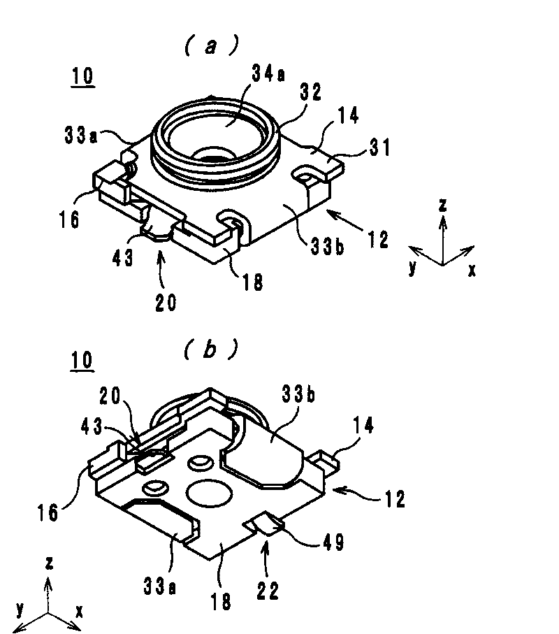
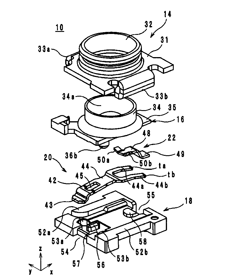
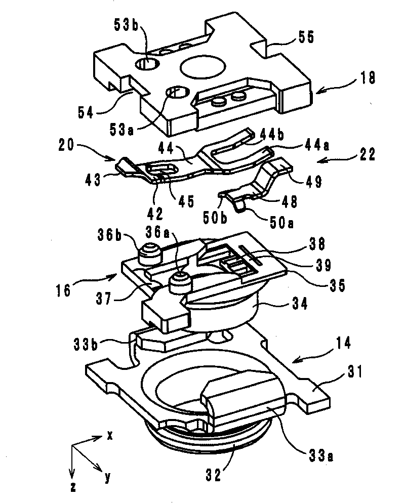
[0026] figure 1 It is an external perspective view of the coaxial connector 10 according to one embodiment of the present invention. in addition, figure 2 as well as image 3 It is an exploded perspective view of the coaxial connector 10 . Hereinafter, details of the coaxial connector (coaxial receiver) 10 will be described. exist Figure 1 to Figure 3 Herein, the direction in which the external terminal 14 , the upper case 16 and the lower case 18 overlap is the z-axis direction. The positive direction of the z-axis is the direction from the lower case 18 toward the external terminal 14 . In addition, the direction in which the movable terminals 20 and the fixed terminals 22 are arranged is the x-axis, and the direction perpendicular to the x-axis and the z-axis is the y-axis. The positive direction of the x-axis is the dire...


PUM


Abstract

The invention provides a coaxial connector with good high-frequency characteristic, a body (14) is formed with a hole for being inserted with a probe; a fixing terminal (22) is fixed on the body (14); a movable terminal (20) includes a fixing part (42) fixed on the body (14) and a plate spring part (44) which extends toward the fixing terminal (22) from the fixing part (42) and is contacted with the fixing terminal (22) and the body (14) at front ends (ta, tb). The plate spring part displaces to the direction away from the fixing terminal (22) by the probe.

Description

technical field [0001] The present invention relates to a coaxial connector, and more particularly, to a coaxial connector that is incorporated into a mobile communication device such as a mobile phone to switch signal paths. Background technique [0002] As a conventional coaxial connector, the coaxial connector described in patent document 1 is known. Below, while referring to the attached Figure 1 Side description of the coaxial connector. Figure 10 It is a cross-sectional structure diagram of the coaxial connector 110 described in patent document 1. Figure 11 It is an external perspective view showing the shell 118 of the coaxial connector 110 , the movable terminal 120 and the fixed terminal 122 . Figure 10 as well as Figure 11 In the figure, the direction in which the external terminal 114 and the shells 116 and 118 overlap is the z-axis. In addition, the direction in which the movable terminals 120 and the fixed terminals 122 are arranged is defined as the x-...

Claims


Application Information

Patent Timeline
IPC IPC(8): H01R24/02H01R13/71
CPCY10S439/944H01R2103/00H01R24/44H01R24/50H01R2201/02
Inventor 星场宽之浦谷力
Owner MURATA MFG CO LTD
Why Eureka
Try Eureka