An automatic braking device for rope transmission

A technology of automatic braking and rope transmission, applied in safety belts, life-saving equipment, etc., can solve the problems of casualties, large methods, and low safety, and achieve the effects of ensuring life safety, simple structure, and convenient operation

Inactive Publication Date: 2011-12-21
DONGGUAN TIANNAN OPTICAL TECH
View PDF0 Cites 0 Cited by
  • Summary
  • Abstract
  • Description
  • Claims
  • Application Information

AI Technical Summary

Problems solved by technology

The former means that the electromagnetic brake uses the braking motor to brake the rope and has the following technical defects: 1) It depends on electromagnetic conditions, and electromagnetic braking requires an external power supply. If the power is insufficient or fails during long-term high-altitude or field operations, the braking device will Out of control, can not ensure the safety of personnel, and the application is limited; 2) The braking method of the motor is larger than the force required to lock the transmission rope, and the braking energy consumption is high; 3) The electromagnetic brake with a simple structure can only be released and locked. Tight two states, can not realize the function of safe descent controlled by the operator
The latter means that some current mechanical locking mechanisms that use eccentric wheels, connecting rods and related components all use manual braking, that is, the operator needs to pull the handle and apply a certain force before braking. There are the following technical defects: 1) Braking requires the operator to continuously apply external force, the braking efficiency is low, and it is not easy to operate; 2) The structure is complex, large in size and heavy in weight, which affects the load capacity of the rope climbing device; In the event of a situation, if the operator does nothing or makes an error due to misjudgment or nervousness, it is likely to fall freely immediately, causing casualties and low safety.

Method used


Image

  • An automatic braking device for rope transmission
  • An automatic braking device for rope transmission
  • An automatic braking device for rope transmission

Examples


Embodiment Construction

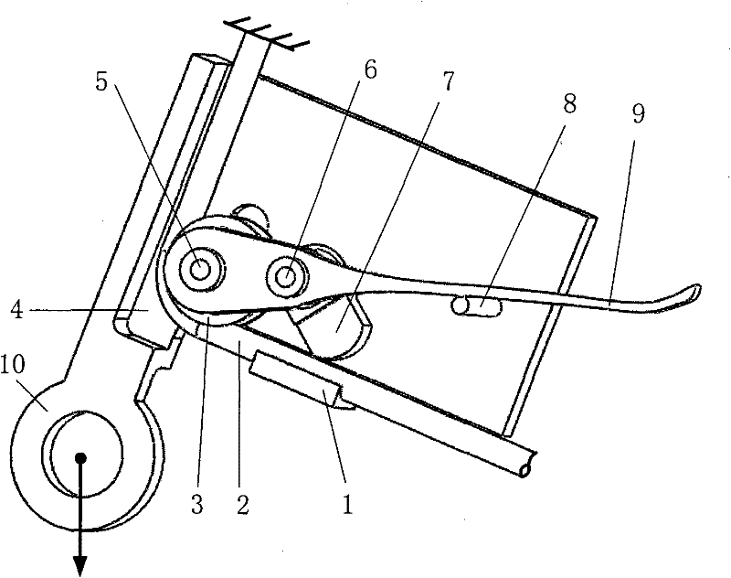
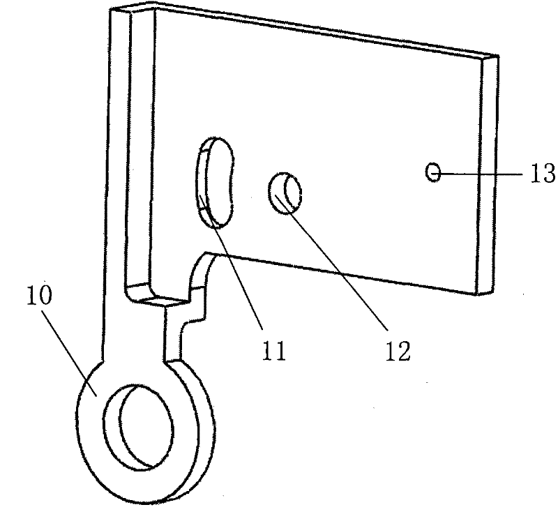
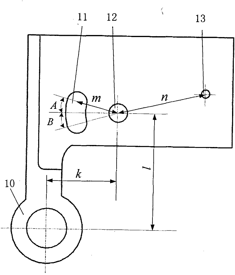
[0011] The automatic braking device of the rope transmission that the present invention proposes, its structure is as follows: figure 1 As shown, it includes base plate 4, steering wheel 3, briquetting block 7, pressure groove 1, handle 9 and stop pin 8. One side bottom of base plate 4 is provided with the annulus 10 of hanging weight, has movable shaft hole 11, fixed axis hole 12 and stop pin hole 13 on the base plate 4, and pressure groove 1 is fixed on the bottom of base plate 4. One end of the handle 9 and the steering wheel 3 are coaxially fixed on the moving shaft 5, and the moving shaft 5 is inserted in the oblong moving shaft hole 11. The middle part of the handle 9 and the briquetting block 7 are fixed in the fixed shaft hole 12 through the fixed shaft 6, the stop pin 8 is inserted in the stop pin hole 13, one end of the briquetting block 7 is relatively fixed with the moving shaft 6, and the other end of the handle 9 rests on the on the stop pin 8.

[0012] In the ...


PUM


Abstract

The invention relates to an automatic braking device driven by a rope, which belongs to the technical field of mechanical manufacturing equipment. In this automatic braking device, a side bottom of the base plate is provided with a ring for hanging heavy objects, and the base plate is provided with a moving shaft hole, a fixed axis hole and a stop pin hole, and the pressure groove is fixed on the bottom of the base plate. One end of the handle and the steering wheel are coaxially fixed on the moving shaft, and the moving shaft is inserted in the oblong moving shaft hole. The middle part of the handle and the pressing block are fixed in the fixed shaft hole through the fixed shaft, and one end of the pressing block is relatively fixed with the moving shaft. The stop pin is inserted in the stop pin hole, and the other end of the handle rests on the stop pin. With the automatic braking device of the present invention, when emergency braking is required, the device can realize automatic braking only by pulling off the stop pin, and the operator can move the handle to achieve safe descent, thereby ensuring the safety of the operator. The brake device of the invention has the advantages of simple structure, small volume, light weight, automatic braking, reliable braking, high efficiency and convenient operation.

Description

technical field [0001] The invention relates to an automatic braking device driven by a rope, which belongs to the technical field of mechanical manufacturing equipment. Background technique [0002] The portable and integrated automatic rope climbing device is mainly used in high-altitude operations and field rapid lifting and emergency rescue. It is necessary to ensure the safety of the operator, which requires a braking device. In the case of insufficient power supply or failure of other devices Emergency safety braking, and it can also realize the function that allows the operator to achieve safe descent through convenient operation. At present, there are two types of devices with similar technical characteristics that are applied to portable and integrated automatic rope climbing devices: electromagnetic brakes brake the ropes through braking motors and mechanical locking mechanisms using eccentric wheels, connecting rods and related components Direct braking rope and ...

Claims


Application Information

Patent Timeline
Patent Type & Authority Patents(China)
IPC IPC(8): A62B35/00
Inventor 顾俊红张宏生
Owner DONGGUAN TIANNAN OPTICAL TECH
Why Eureka
Try Eureka