Caster emitting device

A technology of injection molding machine and piston, which is applied in the field of injection device of injection molding machine to achieve the effect of stable operation, sensitive injection and stop, and simple structure

Inactive Publication Date: 2010-07-07
曾明松
View PDF0 Cites 8 Cited by
  • Summary
  • Abstract
  • Description
  • Claims
  • Application Information

AI Technical Summary

Problems solved by technology

[0004] The technical problem to be solved by the present invention is to overcome the shortcomings of current products and provide an injection device for injection molding machines that has high stability, is more sensitive between injection and stop, is not easy to wear, and can ensure the molding accuracy of the injection molding machine for a long time.

Method used


Image

  • Caster emitting device
  • Caster emitting device

Examples


Embodiment Construction

[0012] Below in conjunction with accompanying drawing, the present invention will be further described:

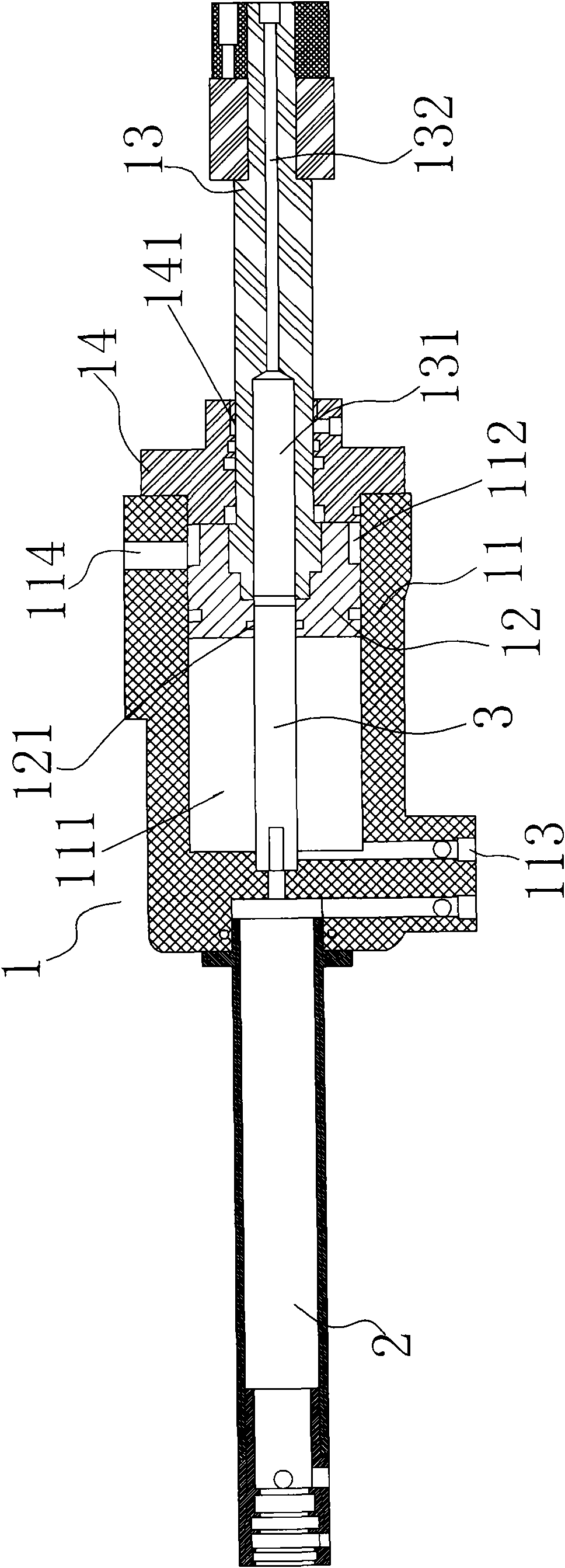
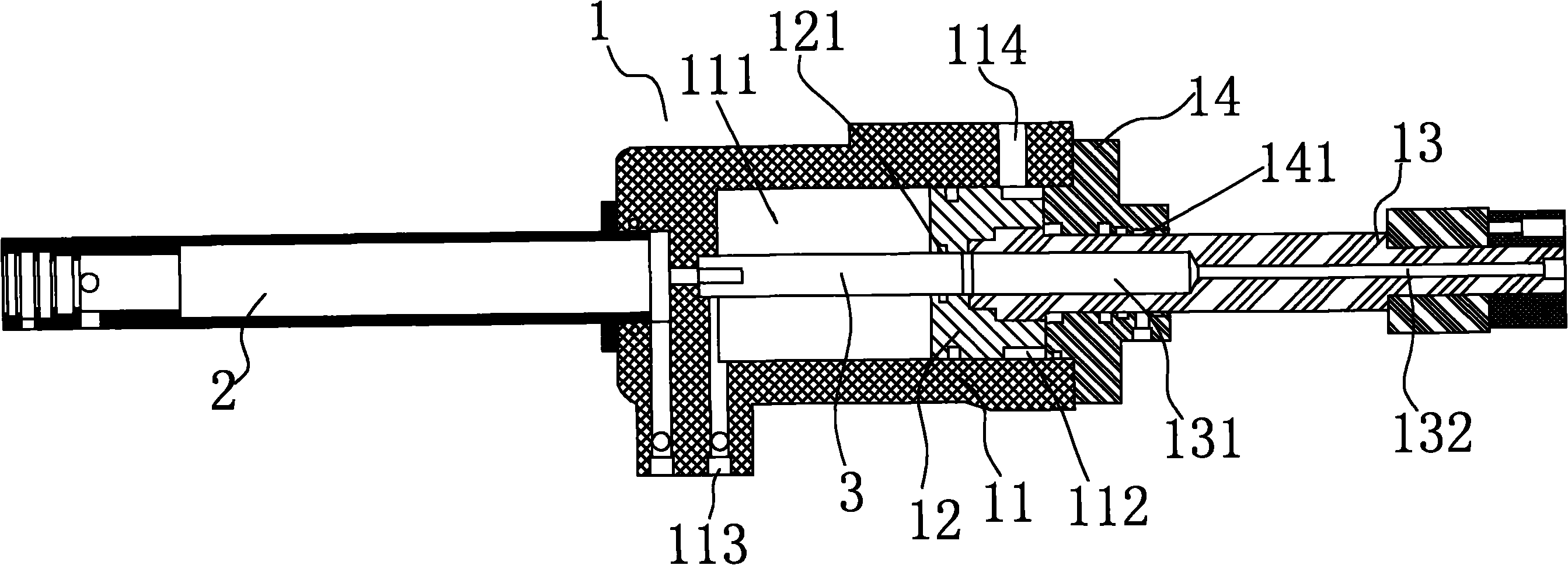
[0013] Such as figure 1 As shown, the present invention includes: an injection cylinder 1 , a hydraulic motor for pumping oil, and a guide rod 3 .

[0014] The injection cylinder 1 includes: a cylinder barrel 11 , a piston 12 installed in the cylinder barrel 11 , a piston rod 13 fixedly connected with the piston 12 , and a cylinder cover 14 . The cylinder head 14 covers the opening of the cylinder barrel 11 , and the cylinder head 14 is provided with a through hole 141 for the piston rod 13 to move left and right.

[0015] The piston 12 divides the cylinder 11 into an air chamber 111 and an oil chamber 112, wherein the air chamber 111 has an air hole 113 communicating with the outside, and the oil chamber 112 has an oil hole 114 communicating with the outside; There is an ejection oil cylinder 131 corresponding to the piston guide hole 121 and cooperating with the guide ...


PUM


Abstract

The present invention relates to the technical field of a caster, in particular to a caster emitting device. An emitting oil cylinder in the caster emitting device comprises a cylinder barrel, a piston arranged in the cylinder barrel and a piston rod fixedly connected with the piston, wherein a guide rod is arranged in the cylinder barrel, and the piston matched with the guide rod can move forward and rearward along the guide rod. The guide rod can enable the whole caster emitting device to run more stably, and enables more flexible between emission and stopping; however, the guide rod is not easy to wear; the push force of pressure oil can be sufficiently used; and further, the forming precision of the caster can be ensured for a long time. The present invention has the advantages of simple structure, easy manufacture, even piston stress and large marketing competitive power.

Description

Technical field: [0001] The invention relates to the technical field of injection molding machines, in particular to an injection molding machine injection device. Background technique: [0002] At present, the general injection molding machine injection device driven by oil pressure includes an oil pressure cylinder, which drives the piston to move through the oil pressure, and drives the piston rod through the piston. When the piston in the injection device of the injection molding machine moves back and forth in the cylinder, the piston slides back and forth against the inner wall of the cylinder. However, in actual work, the piston tends to tilt when it slides left and right under the push of oil pressure, and the piston will directly generate pressure on the inner wall of the cylinder. produce wear and tear. In order to prevent this from happening, the usual practice is to process the piston wider so that it can fully cooperate with the inner wall of the cylinder to a...

Claims


Application Information

Patent Timeline
Patent Type & Authority Applications(China)
IPC IPC(8): B29C45/53
Inventor 曾明松
Owner 曾明松
Why Eureka
Try Eureka