Hydraulic oil cylinder

A technology of hydraulic cylinders and cylinder barrels, which is applied in the field of hydraulic cylinders and can solve problems such as easy swinging of piston rods, mixing, and affecting work performance

Inactive Publication Date: 2010-07-07
佛山市沃德森板业有限公司
View PDF0 Cites 10 Cited by
  • Summary
  • Abstract
  • Description
  • Claims
  • Application Information

AI Technical Summary

Problems solved by technology

[0002] Wood-based panel multi-layer presses all have a simultaneous closing device, and there is an important control part in the simultaneous closing system - the hydraulic cylinder. The current hydraulic cylinder body generally does not have the function of adjusting the stroke, and when the hydraulic cylinder is connected

Method used


Image

  • Hydraulic oil cylinder
  • Hydraulic oil cylinder

Examples


Embodiment approach

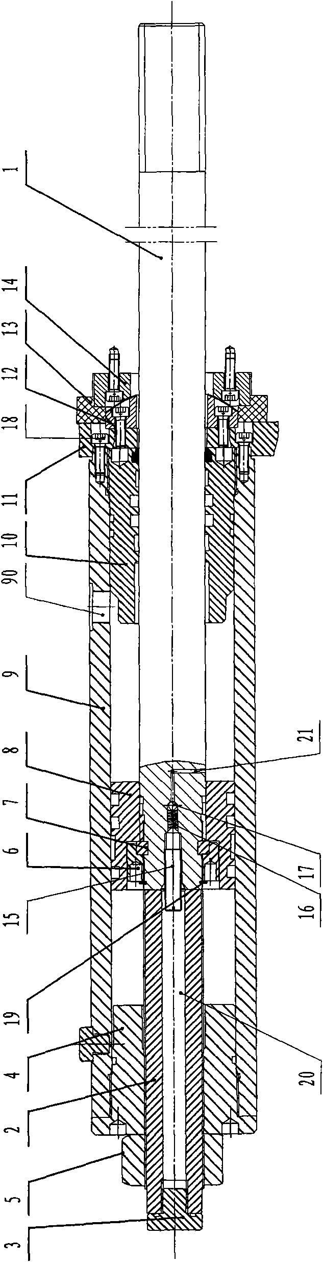
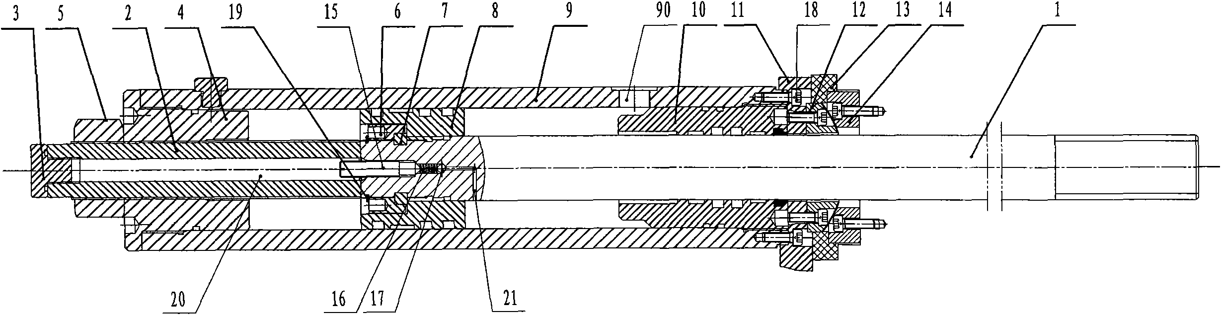
[0015] Implementation: such as figure 1 As shown, the hydraulic cylinder described in this embodiment is mainly composed of a cylinder tube 9, a rear end cover 4, a piston rod 1, a piston 8, and a front end cover composed of a guide sleeve 10 and a stop sleeve 11. The guide sleeve 10 is connected to the cylinder tube 9 in a sealed manner. The stop sleeve 11 is firmly connected to the front end of the cylinder tube 8 through a connecting screw 18. The cylinder wall of the cylinder tube 9 is provided with a hydraulic oil pipe connection port 90, and the piston 8 passes through a compression nut 6, a key 7. The shaft is fixed on the end of the piston rod 1 with a retaining ring 19. A screw hole is opened in the center of the rear end cover 4, and a limit screw 2 is installed on the screw hole. The outer end of the limit screw 2 is fixed by a lock nut 5. The length of the limit screw 2 extending into the cylinder 9 can be adjusted. Adjust the stroke of the piston rod 1. When conn...


PUM


Abstract

The invention relates to a hydraulic oil cylinder which comprises a cylinder barrel, a rear end cover, a front end cover, a piston rod and a piston. The hydraulic oil cylinder is characterized in that: a screw hole is arranged in the center of the rear end cover, a position-limiting screw rod which can adjust the stroke of the piston rod is arranged on the screw hole, and the outer end of the position-limiting screw rod is fixed by a locking nut. A through hole is arranged in the center of the position-limiting screw rod, an installation hole is arranged at the rear end of the piston rod, an air exhaust valve is arranged on the installation hole, and a channel which is arranged at the front end of the air exhaust valve is connected with an inner cavity of the cylinder barrel. The air exhaust valve comprises an air exhaust screw, a spring and a steel ball. The steel ball leans against the channel under the action force of the spring. A blocking head is arranged at the rear end of the position-limiting screw rod. The front end cover comprises a guide sleeve and a stop sleeve, the guide sleeve is connected with the cylinder barrel in a sealing manner, and the stop sleeve is connected with the front end of the cylinder barrel by a connecting piece in a fastening manner. The stop sleeve is provided with an adjusting device which can carry out automatic centering on the piston rod. Hydraulic oil with the above structure can adjust the stroke of the oil cylinder, and the running of the oil cylinder is stable.

Description

Technical field [0001] The invention belongs to the field of hydraulic equipment manufacturing, and specifically relates to a hydraulic oil cylinder. Background technique [0002] The wood-based panel multilayer presses all have simultaneous closing devices. At the same time, there is an important control component in the closing system-hydraulic cylinders. The current hydraulic cylinder bodies generally do not have the function of adjusting the stroke, and the hydraulic cylinders generally There is air in the cylinder, which is directly connected to the oil pipe. The air in the cylinder will be mixed into the hydraulic oil and affect the working performance. In addition, due to errors caused by processing and equipment, the piston rod is easy to swing, or deform and scratch the cylinder. Summary of the invention [0003] The purpose of the present invention is to provide a hydraulic cylinder with adjustable cylinder stroke and stable operation. [0004] The purpose of the present...

Claims


Application Information

Patent Timeline
IPC IPC(8): F15B15/24
Inventor 吴和平吉发浦强严荣陈淼常明冯莹莹
Owner 佛山市沃德森板业有限公司
Why Eureka
Try Eureka