
Apparatus and method for monitoring demagnetization state of permanent magnet of permanent magnet motor

A permanent magnet motor and demagnetization state technology, which is applied in the direction of magnetic performance measurement, etc., can solve the problems of system safety hazards, failure to diagnose the demagnetization of permanent magnets, and inability to obtain accurate information of permanent magnets, etc., and achieve the effect of accurate and fast detection

Inactive Publication Date: 2010-07-07
SHANGHAI DAJUN TECH
View PDF0 Cites 15 Cited by
  • Summary
  • Abstract
  • Description
  • Claims
  • Application Information

AI Technical Summary

Problems solved by technology

However, the currently used monitoring devices mostly use temperature sensors to measure the temperature of the armature windings to determine whether the permanent magnets are magnetically normal or not. Since the temperature of the armature windings is not consistent with the temperature of the permanent magnets, this method cannot be obtained. Accurate information on the magnetism of the permanent magnet, and once the permanent magnet has been demagnetized, the temperature sensor cannot diagnose whether the permanent magnet is demagnetized
Therefore, the existing detection and monitoring methods cannot report to the police and deal with them in time, which will cause great security risks to the system.

Method used


Image

  • Apparatus and method for monitoring demagnetization state of permanent magnet of permanent magnet motor
  • Apparatus and method for monitoring demagnetization state of permanent magnet of permanent magnet motor
  • Apparatus and method for monitoring demagnetization state of permanent magnet of permanent magnet motor

Examples


Embodiment 1

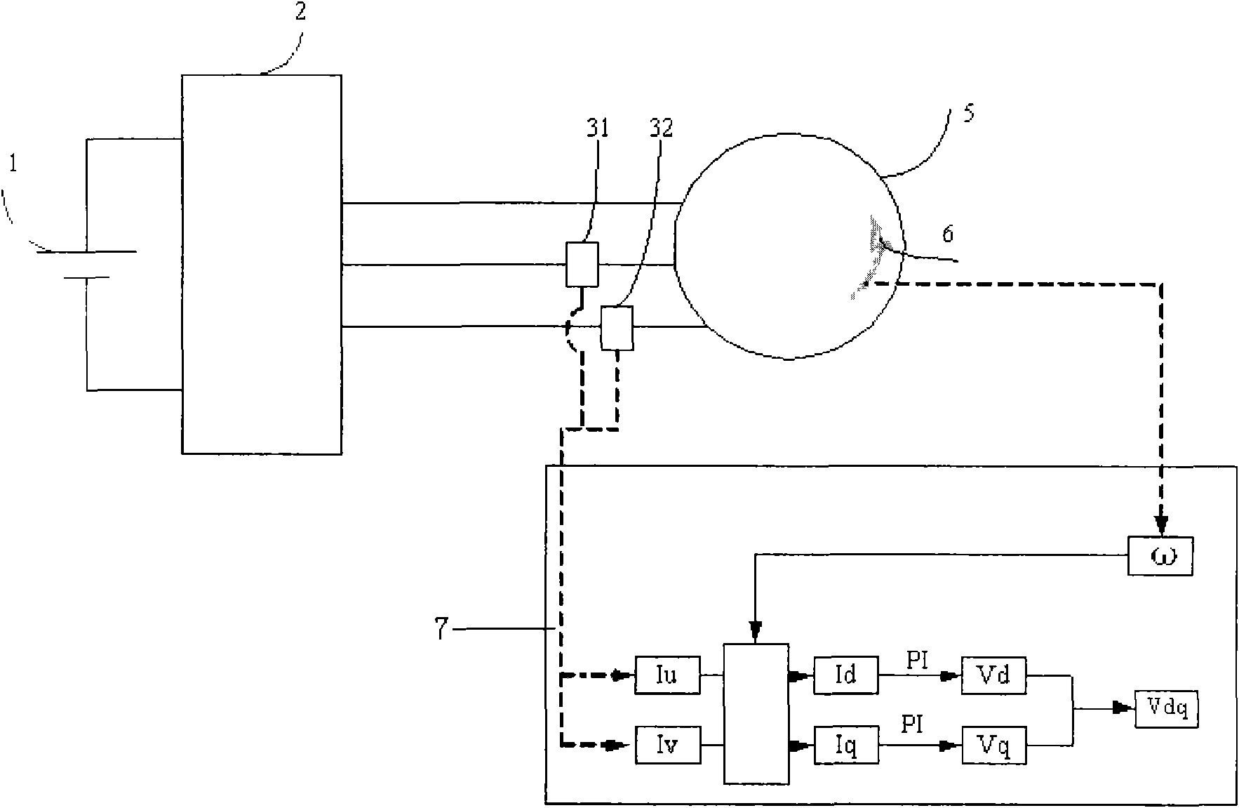
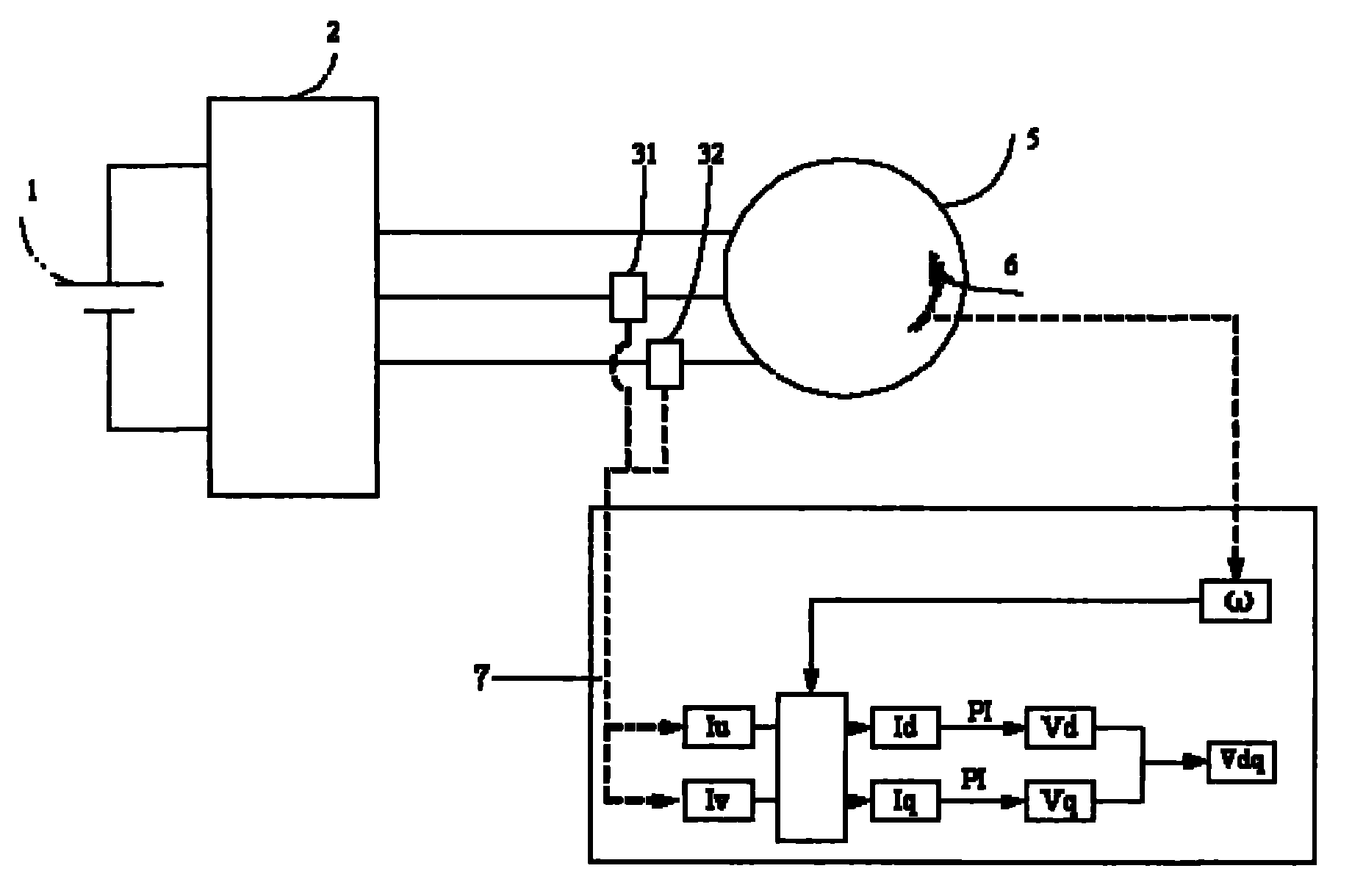
[0020] A demagnetization state monitoring device of a permanent magnet of a permanent magnet motor, comprising a battery 1, an inverter 2, a U-phase current sensor 31, a V-phase current sensor 32, a permanent magnet motor 5, a speed sensor 6 and a microprocessor 7, such as figure 1 As shown, the specific structure is: the battery 1 is connected to the inverter 2 with wires, the direct current output by the battery is converted into three-phase alternating current through the inverter 2, and then connected to the permanent magnet motor 5 with wires, and the inverter 2 and the inverter 2 are connected. Among the three-phase wires of the motor 5, the U-phase wire and the V-phase wire are respectively connected in series with a U-phase current sensor 31 and a V-phase current sensor 32, and a speed sensor 6 is parallelly connected to the permanent magnet motor 5, and a U-phase current sensor 31 and a V-phase current sensor 31 are connected in series. Both the current sensor 32 and t...


PUM


Abstract

The invention relates to the magnetic material detection field, in particular to an apparatus and a method for monitoring a demagnetization state of a permanent magnet of a permanent magnet motor. The apparatus for monitoring the demagnetization state of the permanent magnet of the permanent magnet motor comprises a battery (1), an inverter (2) and a permanent magnet motor (5), and is characterized by also comprising a U phase current sensor (31), a V phase current sensor (32), a speed sensor (6) and a microprocessor (7), a U phase line and a V phase line are respectively connected with a phase current sensor in series, the speed sensor (6) is connected on the permanent magnet motor (5) in parallel, and the U phase current sensor (31), the V phase current sensor (32) and the speed sensor (6) are all connected with the microprocessor (7) by leads. The invention can accurately and rapidly detect performances of the permanent magnet, and does not influence the control performances of the system.

Description

technical field [0001] The invention relates to the field of magnetic material detection, in particular to a demagnetization state monitoring device and method for permanent magnets of permanent magnet motors. Background technique [0002] The motor is generally composed of a stator and a rotor. The stator generates an alternating magnetic field. When the rotor is driven by the prime mover, the rotor winding cuts the magnetic force lines of the stator's alternating magnetic field to induce an induced electromotive force. At this time, it is a generator; when the rotor is input with electric energy, the rotor The winding is pulled by the alternating magnetic field and rotates to output torque externally. At this time, it is a motor. The alternating magnetic field on the stator used to be generated by inputting excitation current from the outside. Based on the continuous improvement of energy saving requirements and the continuous application of high magnetic materials, motors...

Claims


Application Information

Patent Timeline
Patent Type & Authority Applications(China)
IPC IPC(8): G01R33/12
Inventor 徐性怡庄朝晖张玉柱
Owner SHANGHAI DAJUN TECH
Learn More