
Optical modulator with pixelization patterns

An optical modulator and pixel technology, which is applied in optics, optical components, nonlinear optics, etc., can solve the problems of increased manufacturing cost and large MCP volume, and achieve the goal of maintaining simplicity, preventing resolution degradation, and improving image resolution Effect

Active Publication Date: 2010-07-07
SAMSUNG ELECTRONICS CO LTD
View PDF2 Cites 4 Cited by
  • Summary
  • Abstract
  • Description
  • Claims
  • Application Information

AI Technical Summary

Problems solved by technology

Therefore, the manufacturing cost is increased and the volume of the MCP is too large

Method used


Image

  • Optical modulator with pixelization patterns
  • Optical modulator with pixelization patterns
  • Optical modulator with pixelization patterns

Examples


Embodiment Construction

[0030] Reference will now be made in detail to the exemplary embodiments, examples of which are illustrated in the accompanying drawings, wherein like reference numerals refer to like elements throughout. In this regard, the present exemplary embodiments may have different forms and should not be construed as being limited to the descriptions set forth herein. Accordingly, the exemplary embodiments are merely described below, by referring to the figures, to explain aspects of the present description.

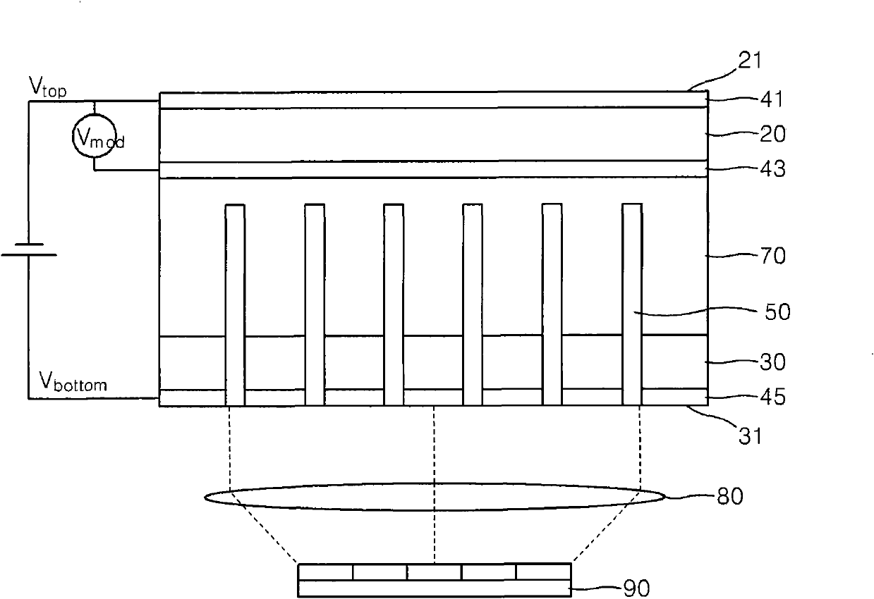
[0031] figure 1 A semiconductor-based optical modulator according to an exemplary embodiment is schematically shown.

[0032] refer to figure 1 , a semiconductor-based optical modulator is a device that modulates an incident infrared (IR) image and transmits the modulated image. The semiconductor-based optical modulator includes: an optical-electrical (O-E) conversion element 20 that uses the photoelectric effect to convert the input The optical image of the optical image is ...


PUM


Abstract

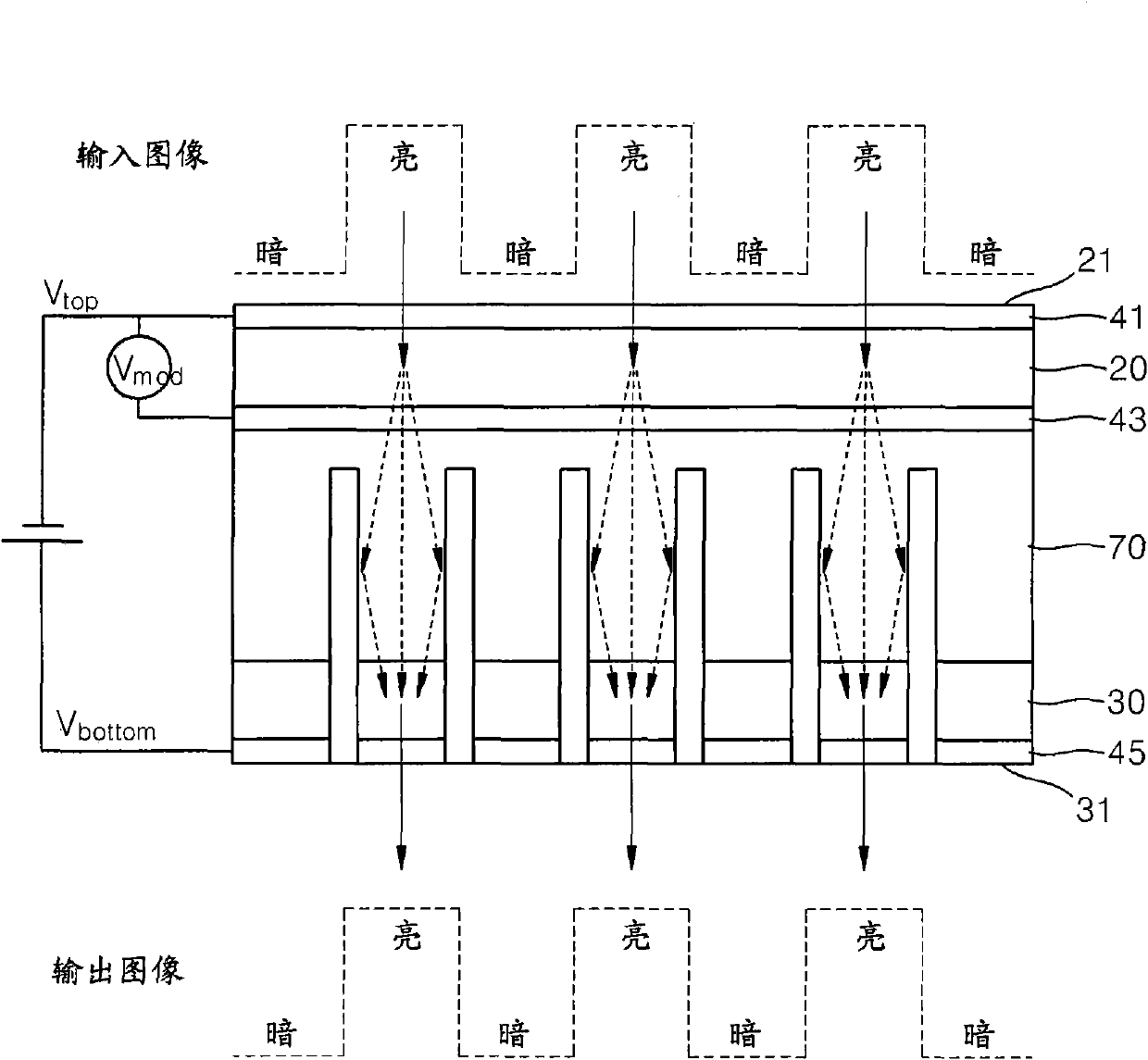
Provided is an optical modulator having pixelization patterns. The optical modulator includes an optical-electric (O-E) conversion element converting input optical images to current signals using the photoelectric effect, and an electric-optical (E-O) conversion element that emits light using the current signals transferred from the O-E conversion element. Trenches are formed from at least a surface of the optical modulator to a predetermined depth in the optical modulator so as to block or reduce electrical interference between pixels when the electric signals are transferred from the O-E conversion element to the E-O conversion element.

Description

technical field [0001] One or more exemplary embodiments relate to an optical modulator, and more particularly, to an optical modulator having a pixelization pattern to obtain image modulation with high resolution. Background technique [0002] Optical-Electrical-Optical (O-E-O) modulators receive optical information (images) to convert optical information into electrical information, modulate electrical information, and output optical information (images), optical-electrical-optical (O-E-O) modulators can have the following Performs the functions of modulating, converting wavelength, and amplifying light at high speed, therefore, optical-electrical-optical (O-E-O) modulators have been used as core components in three-dimensional (3D) cameras, laser radar (LADAR), infrared (IR) imaging . [0003] The O-E-O modulator is operated by a mechanism of receiving an image having a wavelength of about 800nm ​​to 1700nm (i.e., infrared (IR) band), generating a current using the photo...

Claims


Application Information

Patent Timeline
Patent Type & Authority Applications(China)
IPC IPC(8): G02F1/00
CPCH01L31/153H01L31/14H01L31/145G02B26/001G02B26/08B81B2207/015
Inventor 朴勇和赵龙哲赵秀行
Owner SAMSUNG ELECTRONICS CO LTD
Learn More