Check patentability & draft patents in minutes with Patsnap Eureka AI!

Low-voltage energy band gap reference circuit

A technology of reference circuit and energy bandgap, which is applied in the direction of adjusting electrical variables, control/regulating systems, instruments, etc., and can solve the problems of increasing circuit complexity and manufacturing cost, and increasing the overall system circuit area.

Inactive Publication Date: 2010-07-07
NOVATEK MICROELECTRONICS CORP
View PDF0 Cites 4 Cited by
  • Summary
  • Abstract
  • Description
  • Claims
  • Application Information

AI Technical Summary

Problems solved by technology

And this additional circuit is often made of complex analog components, which will increase the circuit area of ​​the overall system, and the circuit complexity and production cost will also increase accordingly.

Method used


Image

  • Low-voltage energy band gap reference circuit
  • Low-voltage energy band gap reference circuit
  • Low-voltage energy band gap reference circuit

Examples


no. 1 example

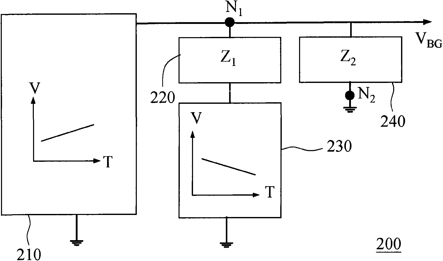
[0019] Please refer to figure 2 , a block diagram of a bandgap reference circuit according to a first embodiment of the present invention. exist figure 2 Among them, the bandgap reference circuit 200 is used to generate an output reference voltage V BG . The bandgap reference circuit 200 includes: a first reference signal generator 210 , a first impedance 220 , a second reference signal generator 230 and a second impedance 240 . Bandgap reference voltage V BG is substantially independent of temperature, and can vary with the impedance value Z of the first impedance 220 and the second impedance 240 1 and Z 2 To determine the size, as shown in the following example, the output reference voltage V BG A bandgap reference voltage of about 1.25V lower than this standard value can be obtained.

[0020] The first reference signal generator 210 has an output terminal coupled to a first node N1 for generating a first reference signal proportional to absolute temperature (propor...

no. 2 example

[0040] Figure 8 A block diagram of a bandgap reference circuit according to a second embodiment of the present invention is shown. exist Figure 8 , the bandgap reference circuit 800 with figure 2 The main difference of the energy bandgap reference circuit 200 is that: the first reference signal generator 810 of the energy bandgap reference circuit 800 is a circuit with a negative temperature coefficient characteristic and the second reference signal generator 830 is a circuit with a positive temperature coefficient characteristic circuit.

[0041] The first reference signal generator 810 is used to generate a first reference signal complementary to the absolute temperature from the output terminal, such as a current I with a negative temperature coefficient CTAT . Figure 9 , Figure 10 and Figure 11 A practical example of a circuit that can be applied to implement the negative temperature coefficient characteristic of the second embodiment of the present invention i...


PUM


Abstract

The invention relates to an energy band gap reference circuit for generating an output reference voltage irrelevant with temperature and power supply. The low-voltage energy band gap reference circuit comprises a first reference signal generator, a first impedor, a second reference signal generator and a second impedor. The first reference signal generator can generate a first reference signal directly proportional to an absolute temperature. The second reference signal generator generates a second reference signal complementary along with the absolute temperature according to the first reference signal. The second impedor, the first impedor, the second reference signal generator and the first reference signal generator are coupled in parallel between two nodes, and the output reference voltage is supplied by the two nodes, wherein the first impedor and the second reference signal generator are connected with each other in series. According to the invention, the energy band gap reference circuit can be implemented by an extra circuit with low complexity to obtain a changeable and relatively low reference voltage.

Description

technical field [0001] The present invention relates to a bandgap reference circuit, and more particularly to a low voltage bandgap reference circuit. Background technique [0002] The bandgap reference circuit is widely used in integrated circuits, and its typical application is to provide a reference voltage of about 1.25V. The reference voltage is more accurate than the voltage supplied by the external power supply, and it is less affected by temperature changes and variations of the power supply. The energy bandgap reference circuit uses a circuit proportional to the absolute temperature to compensate the negative temperature coefficient of the base-emitter of the bicarrier transistor, so as to obtain a reference voltage that is substantially unaffected by temperature changes. [0003] In order to meet the application requirements of different integrated circuits, it is hoped that a reference voltage lower than the standard value of about 1.25V can be obtained. For exa...

Claims


Application Information

Patent Timeline
IPC IPC(8): G05F3/08
Inventor 杨智勋
Owner NOVATEK MICROELECTRONICS CORP
Features
  • R&D
  • Intellectual Property
  • Life Sciences
  • Materials
  • Tech Scout
  • Unparalleled Data Quality
  • Higher Quality Content
  • 60% Fewer Hallucinations
Learn More