Blood test device and test method

A blood test and blood technology, applied in medical science, temperature sensors, sensors, etc., can solve the problems of unsanitary, stained puncture part 8, etc., and achieve the effect of maintaining cleanliness

Inactive Publication Date: 2010-07-07
PANASONIC HEALTHCARE HLDG CO LTD
View PDF3 Cites 4 Cited by
  • Summary
  • Abstract
  • Description
  • Claims
  • Application Information

AI Technical Summary

Problems solved by technology

[0013] However, in the conventional blood test device 1, when the blood sensor 3 contaminated by the adhered blood 10 is detached from the puncture pa

Method used


Image

  • Blood test device and test method
  • Blood test device and test method
  • Blood test device and test method

Examples


Embodiment approach 1

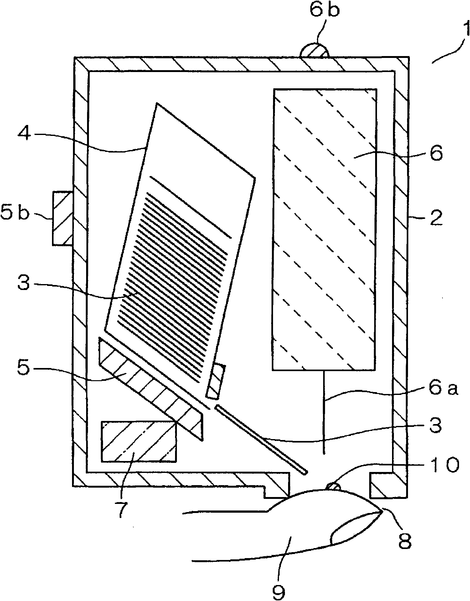
[0057] image 3 It is a sectional view showing the configuration of main parts of the blood test apparatus according to Embodiment 1. First, an overview of the blood test device according to Embodiment 1 will be described.

[0058] image 3 The illustrated blood test device 21 includes, inside a casing 22, blood collection tubes 24 that accommodate blood sensors 23 in a stacked state (see FIGS. Figure 10 ); puncture part 25; laser unit (puncture unit) 26; circuit part 27; negative pressure unit 28; battery 29; Figure 19 ).

[0059] The case 22 includes: a case main body 22a formed of resin or the like in a substantially rectangular parallelepiped shape and opened on one side (here, the bottom side); and a cover 22b rotatably attached to the case via a fulcrum 22c. The main body 22a opens and closes the opening of the case main body 22a.

[0060] Figure 4 It is a cross-sectional view of the blood test device according to Embodiment 1 in a state where the cover is opene...

Embodiment approach 2

[0231] In Embodiment 1, the gap forming means was mainly described as the push-up part provided on the cover body 22b, but in this embodiment, a blood test device provided on the puncturing part will be described. In addition, the basic configuration of the blood test device according to Embodiment 2 is the same as image 3 The shown one corresponds to the same structure as the blood test device 21 of Embodiment 1, and the only difference lies in the structure of the gap forming unit and the first holder and the second holder constituting the puncturing part 25 . Therefore, in this embodiment, the same components as those in Embodiment 1 are assigned the same reference numerals, and detailed description thereof will be omitted.

[0232] Figure 24 It is a perspective view of the first holder forming the puncture part in the blood test device according to Embodiment 2 of the present invention seen from the lower surface side, Figure 25 It is a perspective view of the second ...

Embodiment approach 3

[0269] In this embodiment, the support claw 20c in the first embodiment is omitted from the structure of the first embodiment, and the sensor receiving member 92 installed between the first holder 25a and the second holder 25b is used. A gap is formed between the sensor 23 and the first bracket 25a and the second bracket 25b.

[0270] Figure 27 It is an external perspective view of the sensor receiving member 92 attached between the first holder and the second holder forming the puncturing part of the blood test apparatus according to Embodiment 3, Figure 28 It is a perspective view of the blood sensor 23 inserted into the sensor receiving member 92 . in addition, Figure 29 seen from the back side Figure 28 A diagram of the sensor receiving part 92 is shown, Figure 30It is a perspective view of the first bracket on which the sensor receiving member 92 is suspended. In addition, FIG. 31 is a cross-sectional view of main parts for explaining the operation of the sensor...


PUM


Abstract

A blood test device whereby a used sensor can be discarded without staining the holding part after the completion of blood measurement. In this device, a blood sensor (23), which collects blood oozing out from the punctured skin and analyzes the blood components, is held between a first holder (25a) and a second holder (25b). The second holder (25b) is provided in a movable manner along the direction of closing to and separating from the first holder (25a). By a pressing projection (20b), the second holder (25b) is moved so that the second holder (25b) is separated from the first holder (25a). At the same time, the blood sensor (23) is separated from both of the first holder (25a) and the second holder (25b) and supported by supporting claws (20c). Thus, a gap is formed between the first holder (25a) and the second holder (25b) as described above.

Description

technical field [0001] The present invention relates to a blood test device and a test method using the same. Background technique [0002] Diabetics need to regularly measure blood sugar levels and inject insulin based on the measured blood sugar levels to maintain normal blood sugar levels. In order to maintain this normal blood sugar level, it is necessary to measure the blood sugar level frequently. Therefore, a patient uses a blood test device to puncture the skin of a fingertip or the like to collect a small amount of blood exuded from the skin, and based on the collected blood, components such as a blood sugar level are analyzed. [0003] As conventional blood test devices, the blood test devices disclosed in Patent Document 1 and Patent Document 2 are known. [0004] For example, as a blood test procedure using the blood test device of Patent Document 1, first, the patient puts a finger of one hand (for example, the index finger of the left hand) into contact with ...

Claims


Application Information

Patent Timeline
IPC IPC(8): A61B5/157A61B5/151
CPCA61B5/15136A61B5/150358A61B5/150022A61B5/15113A61B5/14535A61B5/157A61B5/1411A61B5/14532A61B5/1468A61B5/15138A61B5/150099A61B5/150213A61B5/150793A61B5/150824A61B5/150954A61B5/15109
Inventor 高岛哲也藤原雅树三好浩二
Owner PANASONIC HEALTHCARE HLDG CO LTD
Why Eureka
Try Eureka