
Anti-unscrewing and multi-angular fastening apparatuses and methods for surgical bone screw/plate systems

A fastening device and anti-loosening technology, applied in the direction of outer panels, threaded fasteners, screws, etc., can solve problems such as difficult angle arrangement and screw drop

Inactive Publication Date: 2010-07-07
THE UNIV OF NORTH CAROLINA AT CHAPEL HILL +1
View PDF3 Cites 11 Cited by
  • Summary
  • Abstract
  • Description
  • Claims
  • Application Information

AI Technical Summary

Problems solved by technology

[0008] Also, existing screwdriver-like driver tools for inserting fasteners such as screws have limitations in that the screws tend to fall from the driver tool when arranged in an angular orientation, making angular placement difficult

Method used


Image

  • Anti-unscrewing and multi-angular fastening apparatuses and methods for surgical bone screw/plate systems
  • Anti-unscrewing and multi-angular fastening apparatuses and methods for surgical bone screw/plate systems
  • Anti-unscrewing and multi-angular fastening apparatuses and methods for surgical bone screw/plate systems

Examples


Embodiment Construction

[0038] Reference will now be made in detail to the presently preferred embodiments of the subject matter, one or more examples of which are illustrated in the drawings. The various examples are provided to illustrate the subject matter, not by way of limitation. Indeed, features illustrated or described as part of one embodiment can be applied to another embodiment to yield yet another embodiment. The intent is for this topic to cover such modifications and variations.

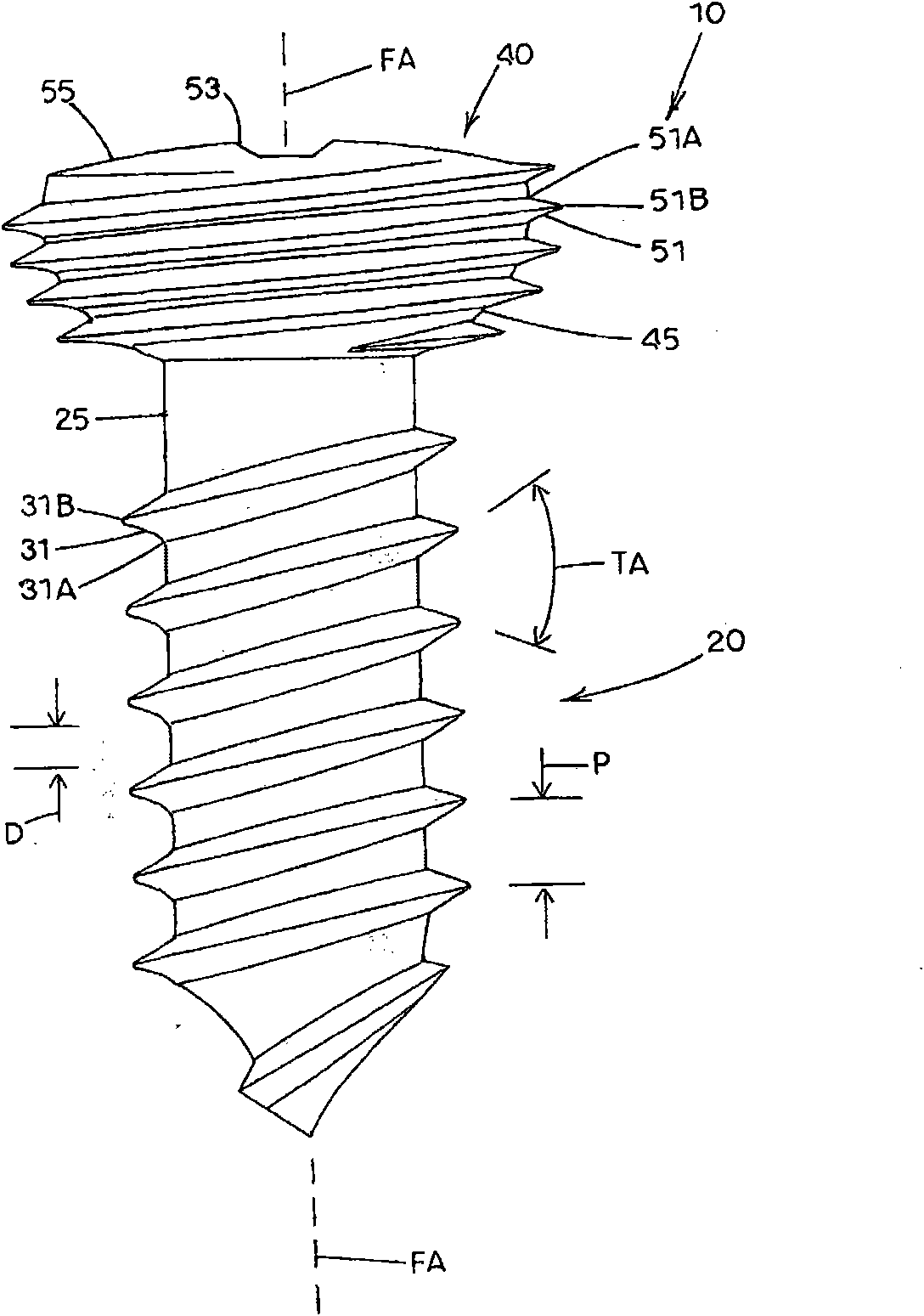
[0039] reference now figure 1 , illustrating one embodiment of a threaded head fastener in accordance with the present disclosure, generally designated 10 . Fastener 10 may be made of any material suitable for withstanding compression, tension, torsion, or other forces encountered during and after application of fastener 10 to a target location. In the context of orthopedic surgery, the fastener 10 is preferably made of a biocompatible metal or metal alloy, such as stainless steel, titanium, chromium or all...


PUM


Abstract

A fastening apparatus includes a fastener and a fastener receiving member. The apparatus enables the fastener to be affixed to the fastener receiving member at a variable insertion angle selected by the user and further provides an anti-unscrewing feature. The fastener includes an elongate section and an adjoining head section having at least one slot therein. The fastener receiving member includes one or more apertures having a contact region through which one or more corresponding fasteners can be inserted. The contact region includes a matrix of protrusions having a density and strength sufficient to render contact region tappable by the thread of the head section of the fastener. The thread on the head section is driven into the contact region at the selected insertion angle. As a result, the protrusions project into the at least one slot to prevent the fastener from backing out of the fastener receiving member. A fastener driver is also disclosed.

Description

[0001] Related applications [0002] This application claims priority to US Patent Application Serial No. 11 / 726,382, filed March 21, 2007, the disclosure of which is incorporated herein by reference in its entirety. technical field [0003] The present invention generally relates to the design of fasteners and elements to which the fasteners are attached. Particular applications of the present disclosure relate to the design and use of bone screw / plate systems during orthopaedic procedures. Background technique [0004] Various techniques exist in the field of orthopaedic surgery for the treatment of fractures. Many known techniques use bone screws and bone fixation plates. In particular, the plate is used to fix the fracture site, and one or more bone screws are inserted through the holes of the plate and penetrate the bone material to fix the plate to the bone material. In addition to the threads typically machined on the main shaft of the screw, it is also known to im...

Claims


Application Information

Patent Timeline
Patent Type & Authority Applications(China)
IPC IPC(8): A61B17/86
CPCA61B17/8888A61B17/888A61B17/8057A61B17/863F16B35/065F16B25/00A61B17/861A61B17/8047A61B17/8886
Inventor 劳伦斯·E.·达昂斯尼古拉斯·F.·华纳
Owner THE UNIV OF NORTH CAROLINA AT CHAPEL HILL
Learn More