
Power supply installation for a railway vehicle

A technology for railway vehicles and facilities, which is applied in the direction of railway vehicles, vehicle parts, vehicle energy storage, etc., and can solve the problem that electrical facilities do not allow vehicles, etc.

Active Publication Date: 2010-07-07
ALSTOM TRANSPORT TECH SAS
View PDF2 Cites 11 Cited by
  • Summary
  • Abstract
  • Description
  • Claims
  • Application Information

AI Technical Summary

Problems solved by technology

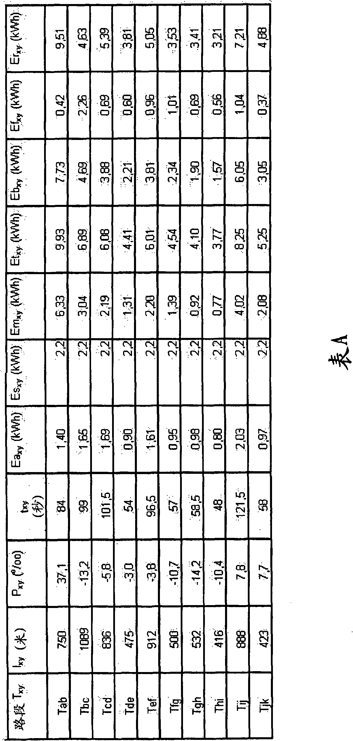
[0037] The applicant's contribution consists in clarifying that the electrical installations of the prior art do not allow the vehicle to travel over the entire vehicle journey, especially on the section between two consecutive stations on which the lane profile has a large length and a large ascent gradient , follow the travel plan

Method used


Image

  • Power supply installation for a railway vehicle
  • Power supply installation for a railway vehicle
  • Power supply installation for a railway vehicle

Examples


Embodiment Construction

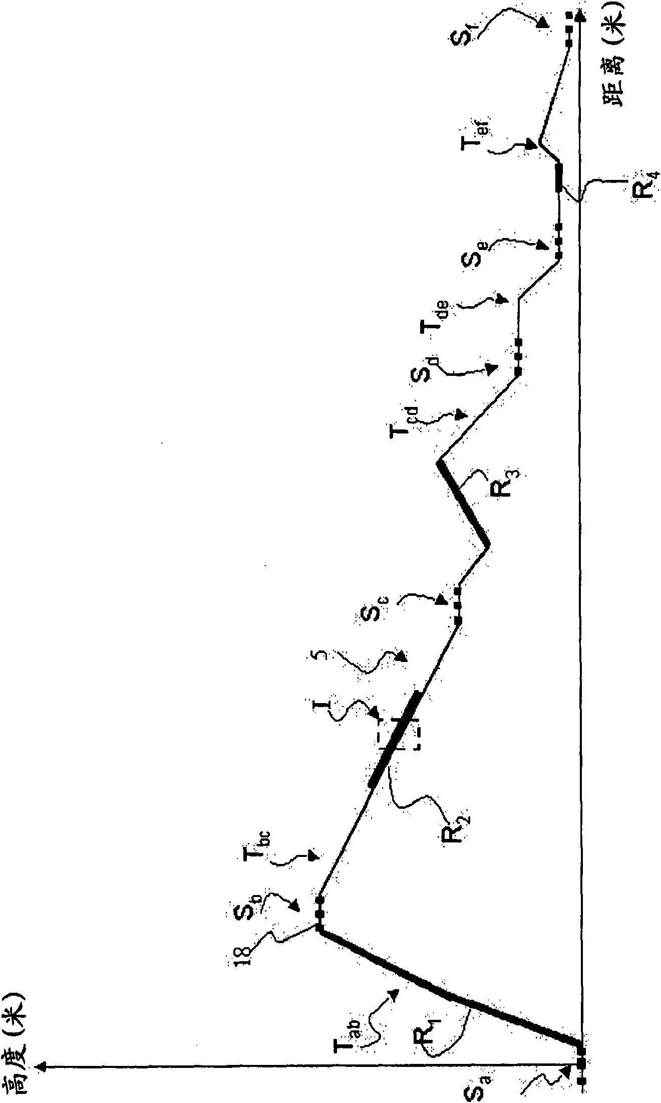
[0086] figure 1 Show the vehicle on lane 5 from station S a to station S f The lane 5 profile on the way.

[0087] figure 1 The embodiment of the present invention shown above is suitable for predicting the lack of electric power of the vehicle equipment, so as to supply enough electric power to the vehicle, so as to follow the previously specified travel plan throughout the journey, regardless of the road section T xy What is the shape of the lane on the road.

[0088] as figure 1 Shown above, known in the art, suitable for allowing passengers to board and unload stops S x , S y All are equipped with station recharging device 18, which is as figure 1 shown by the dotted line above.

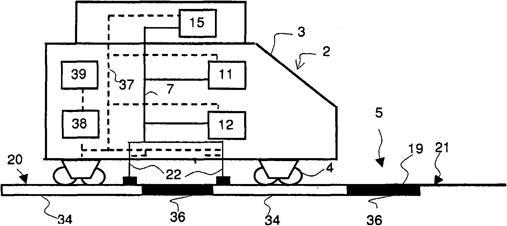
[0089] The station recharging device 18 refers to such a device: when the vehicle is at the stop S x Means for charging the energy storage system 15 and powering the auxiliary equipment 12 when parked and electrically connected to said recharging means.

[0090] Energy storage system 15...


PUM


Abstract

Power supply installation for a railway vehicle (2), the said vehicle (2) being capable of running on a track (5) punctuated with station stops (Sx), in which a device for supplying power via the ground (19) is installed on at least one portion of the track (5) between two successive station stops (Sx) and (Sy), when the energy which the energy storage device (15) is capable of providing to at least one traction motor (11) and to at least one item of auxiliary equipment (12) on a journey Txy between two successive station stops (Sx) and (Sy) is insufficient to comply with a predefined route plan, the said device for supplying power via the ground (19) being capable of supplying the said energy storage device (15), the said at least one traction motor (11) and the said at least one item ofauxiliary equipment (12), when the said vehicle (2) is connected to the said device for supplying power via the ground (19).

Description

technical field [0001] The invention relates to electrical energy supply installations for electric traction public transport vehicles. Background technique [0002] Electric energy supply facilities for trams are known, which include on-board power supply devices for the trams. Such a facility is described in patent application EP0982176 filed by the applicant. The onboard power supply includes an inertial flywheel. It is charged when the vehicle is parked at a station to allow passengers to board and disembark. The recharging of the on-board power supply of the tram is carried out by means of a vehicle-external device arranged at a stop. When the vehicle leaves the station, the vehicle operates autonomously, so that only the on-board power supply supplies power to the vehicle's traction motor and auxiliary equipment such as air conditioning, lighting, etc., to enable the vehicle to travel between two stops and ensure the comfort of passengers. [0003] The applicant ha...

Claims


Application Information

Patent Timeline
IPC IPC(8): B60M1/36B60M3/00B60L11/16B60L5/42B60L50/30
CPCB60L2200/26B60L9/16Y02T10/7027B60M3/00B60M1/36B60L11/16B60L5/42B60L11/1803Y02T10/7005B60L50/30B60L50/51Y02T10/70
Inventor J-P·莫斯科维茨R·克里斯泰勒
Owner ALSTOM TRANSPORT TECH SAS
Learn More