
Cutting trajectory planning method and device for cutting workpiece with flame three-torch device

A cutting track and three-torch technology, which is applied to the cutting track planning and device field for cutting workpieces by a flame three-torch device, and can solve the problems that the cutting device cannot meet the requirements and the like.

Active Publication Date: 2011-12-28
昆山华恒机器人有限公司
View PDF9 Cites 0 Cited by
  • Summary
  • Abstract
  • Description
  • Claims
  • Application Information

AI Technical Summary

Problems solved by technology

However, this device is only an improvement on the three-torch device, and can only be rotated between 0°-360°. In fact, due to the complexity of the cutting pattern, especially in the case of complex nesting, 0°-360° cutting device can not meet the requirements

Method used


Image

  • Cutting trajectory planning method and device for cutting workpiece with flame three-torch device
  • Cutting trajectory planning method and device for cutting workpiece with flame three-torch device
  • Cutting trajectory planning method and device for cutting workpiece with flame three-torch device

Examples


Embodiment Construction

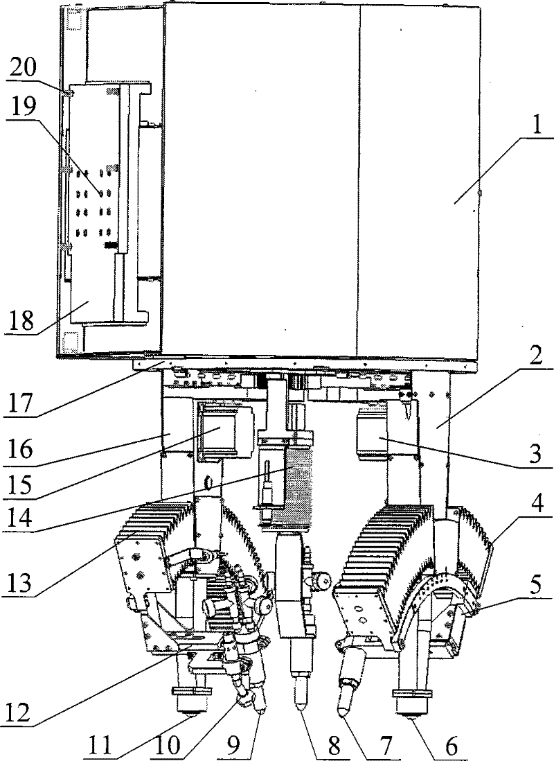
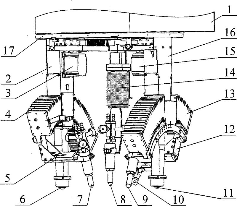
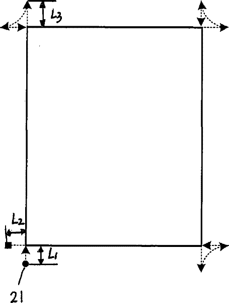
[0044] The technical scheme of the present invention will be further described below in conjunction with the embodiment shown in the accompanying drawings:

[0045] A cutting trajectory planning method for cutting a workpiece using a three-flame cutting torch device, the method includes the following steps:

[0046] Step (1), setting a cutting bevel line on the cutting blank, and the cutting bevel line divides the workpiece into a workpiece forming area and a non-workpiece forming area. Workpieces are divided into inner cut workpieces and outer cut workpieces. For inner cut workpieces, the cutting groove line is the inner contour line of the workpiece to be formed. The inner side of the cutting groove line is the non-workpiece forming area, and the outer side is the workpiece forming area; The workpiece, the cutting groove line is the outer contour line of the workpiece to be formed, the inner side of the cutting groove line is the workpiece forming area, and the outer side is...


PUM


Abstract

The invention relates to a cutting track planning method and device for cutting workpieces with a three-flame cutting torch device. The cutting track planning method can cut cutting workpieces of various shapes. The flame three-torch device can realize the bevel cutting of -360°~360°, and can better meet the needs of complex nesting.

Description

technical field [0001] The invention relates to a cutting track planning method and device for cutting a workpiece with a three-flame cutting torch device. Background technique [0002] my country's factories and enterprises have to decompose tens of millions of tons of steel into parts of various shapes through thermal cutting equipment every year, and carbon steel and oxygen flame cutting are the most important means. At present, CNC flame cutting machines are widely used, not only has high cutting efficiency, but also increases the utilization rate of materials by several percentage points, and its social and economic benefits are considerable. However, the CNC flame cutting machine currently used is generally only controlled by two-axis linkage, and only has a cutting torch perpendicular to the plane of the steel plate, so it can only cut parts with arbitrary contours, but cannot cut out welding grooves on these parts . However, in actual situations, parts often need t...

Claims


Application Information

Patent Timeline
Patent Type & Authority Patents(China)
IPC IPC(8): B23K7/00F23D14/42
Inventor 齐荣怀朱伟郭祖魁张坤刘伟张传根
Owner 昆山华恒机器人有限公司
Learn More