Sweeping mechanism of road sweeper

A cleaning mechanism and road cleaning technology, which is applied in road surface cleaning, cleaning methods, construction, etc., can solve the problem that garbage cannot be smoothly sent into the main rolling cleaning chamber, and achieve the goals of reducing secondary pollution, convenient maintenance and high cleanliness Effect

Inactive Publication Date: 2010-07-14
罗树基
View PDF1 Cites 17 Cited by
  • Summary
  • Abstract
  • Description
  • Claims
  • Application Information

AI Technical Summary

Problems solved by technology

The road sweeper 200620096792.8 and 200820103331. patented by the applicant before have all achieved good expected results through practice; but because the sweeping mechanism auxiliary rolling sweep and main rolling sweep all adopt a single port, due to the large port , so there are some deficiencies, especially when cleaning a relatively wet roa

Method used


Image

  • Sweeping mechanism of road sweeper
  • Sweeping mechanism of road sweeper
  • Sweeping mechanism of road sweeper

Examples


Embodiment Construction

[0027] The present invention is described in detail below in conjunction with accompanying drawing and embodiment:

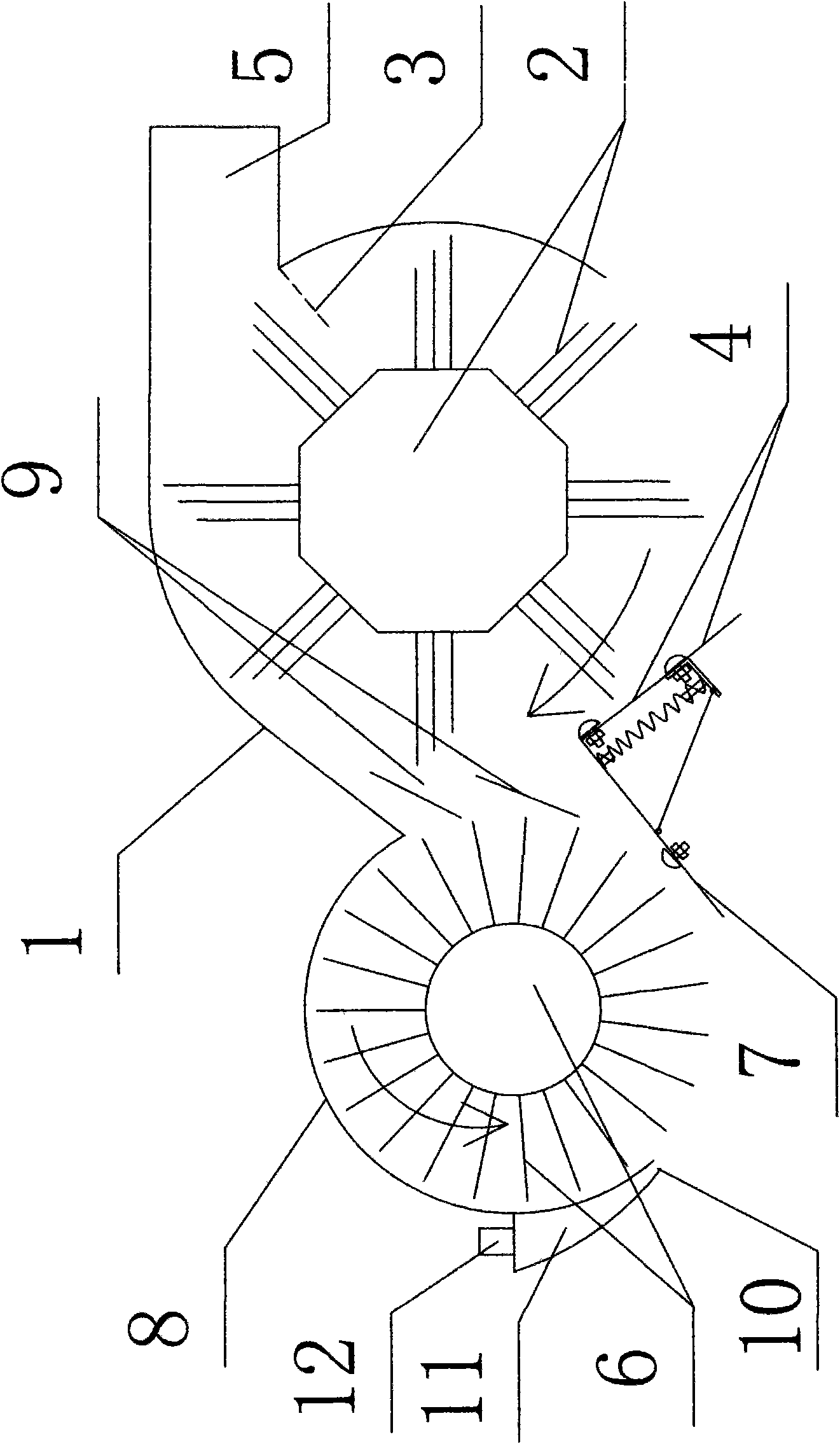
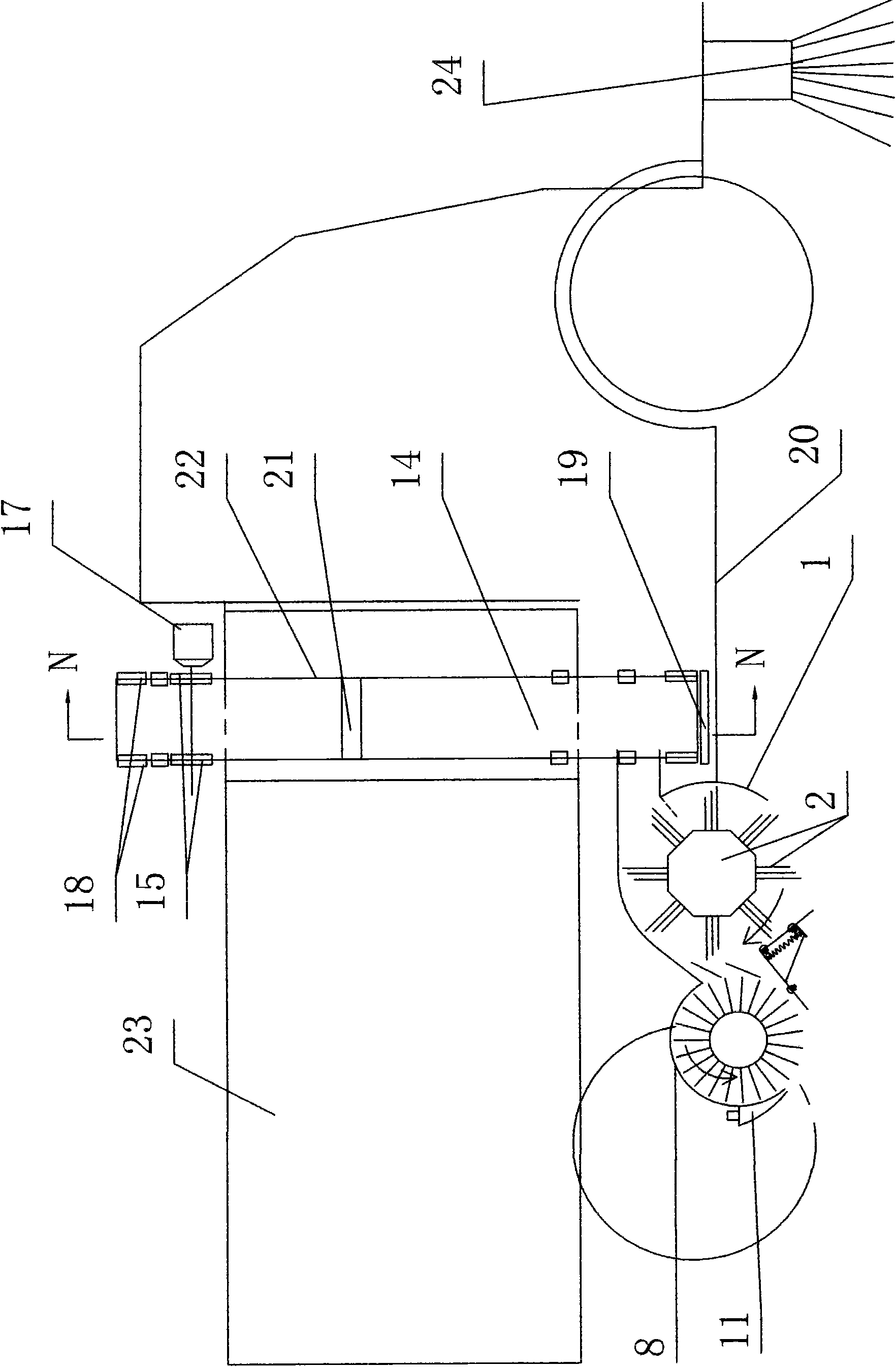
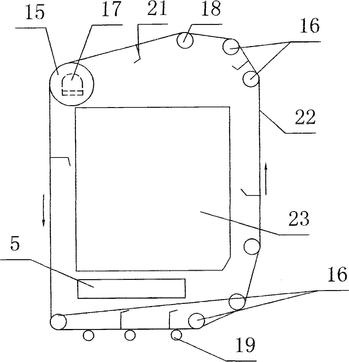
[0028] Such as figure 1 , figure 2 , diagram 2-1 , Figure 2-2 , image 3 , Figure 4 , Figure 5 , Figure 5-1 , Figure 6 , Figure 7 , Figure 7-1 , Figure 8 , Figure 9 , Figure 10 , Figure 11 , Figure 12 , Figure 13 , Figure 14 Shown, be the sweeping mechanism of road cleaning vehicle of the present invention, it is by a main rolling sweep cover 1, main rolling sweep 2, a secondary rolling sweep 6, secondary rolling sweeping cover 8, comb type dust shield, elastic dust guide plate, The transmission system and other components (see the structural principle for details) figure 1). Its structural principle is that the cleaning mechanism of the present invention is installed in the middle section of the bottom of the chassis 20, and the cleaning mechanism of the present invention can be moved up and down on the car body by manipulating...


PUM


Abstract

The invention discloses a sweeping mechanism of a road sweeper, comprising a main rolling-sweep shell, a main rolling sweeper, an assistant rolling-sweep shell and an assistant rolling sweeper. The sweeping mechanism of the road sweeper is characterized in that the adjacent position of the main rolling-sweep shell and the assistant rolling-sweep shell is provided with a communicated louver-type delivery port; the main rolling-sweep shell is communicated and connected with the assistant rolling-sweep shell through the louver-type delivery port arranged on the adjacent position; the main rolling-sweep shell and the assistant rolling-sweep shell are respectively provided with a main rolling-sweep elastic dust guide plate and an assistant rolling-sweep elastic dust guide plate at the lower part of the adjacent position; openings arranged on the main rolling-sweep shell and the assistant rolling-sweep shell relative to the ground are rubbish inlets; the upper part of the main rolling-sweep shell is provided with a main rolling-sweep rubbish outlet so that assistant rolling-sweep rubbishes can be smoothly delivered into a main rolling-sweep cavity, rubbishes inside the main rolling-sweep cavity can not fall into an assistant rolling-sweep cavity in a rolling-sweep way under the action of a dust baffle, thus the invention is especially suitable for sweeping on wetter road surfaces, and a small quantity of rubbishes can not be bonded on a fur brush of the assistant rolling sweeper any more under the action of the dust baffle so as to be smoothly delivered into the main rolling-sweep cavity.

Description

Technical field: [0001] The invention relates to a cleaning mechanism of a road cleaning vehicle, which can clean various garbage in different environments. Background technique: [0002] With the development of urbanization, the work of cleaning and cleaning the streets and alleys of the city is becoming more and more heavy, so there are various series of sweepers to adapt to various environments and the needs of various garbage. The road sweeper 200620096792.8 and 200820103331. patented by the applicant before have all achieved good expected results through practice; but because the sweeping mechanism auxiliary rolling sweep and main rolling sweep all adopt a single port, due to the large port , so there are some deficiencies, especially when cleaning a relatively wet road surface, a small amount of garbage will stick to the brushes of the auxiliary roller sweep and cannot be smoothly sent into the main roller sweep chamber, and there will be dirt in the main roller sweep ...

Claims


Application Information

Patent Timeline
IPC IPC(8): E01H1/08E01H1/04
Inventor 罗树基
Owner 罗树基
Why Eureka
Try Eureka