Water level control method for flush toilet water tank and water saving toilet

A technology for water level control and flushing toilets, applied in flushing toilets, flushing equipment with water tanks, water supply devices, etc., can solve problems such as trouble for users, and achieve the effects of low equipment damage, low manufacturing cost, and long service life

Inactive Publication Date: 2011-10-26
广东博士科技有限公司
View PDF4 Cites 0 Cited by
  • Summary
  • Abstract
  • Description
  • Claims
  • Application Information

AI Technical Summary

Problems solved by technology

Regular repair of the toilet tank has become an indispensable link in the daily life of every family. Sometimes it is even necessary to replace the entire toilet, which brings great trouble to the user.

Method used


Image

  • Water level control method for flush toilet water tank and water saving toilet
  • Water level control method for flush toilet water tank and water saving toilet
  • Water level control method for flush toilet water tank and water saving toilet

Examples


Embodiment 1

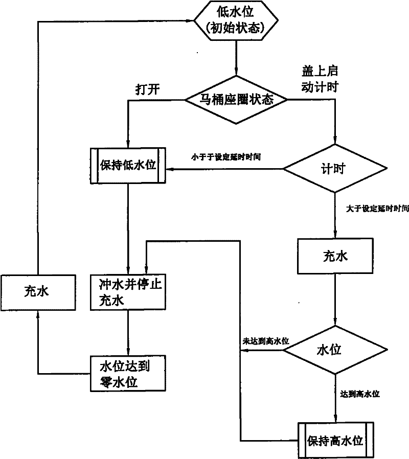
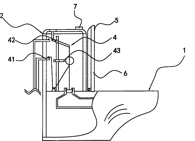
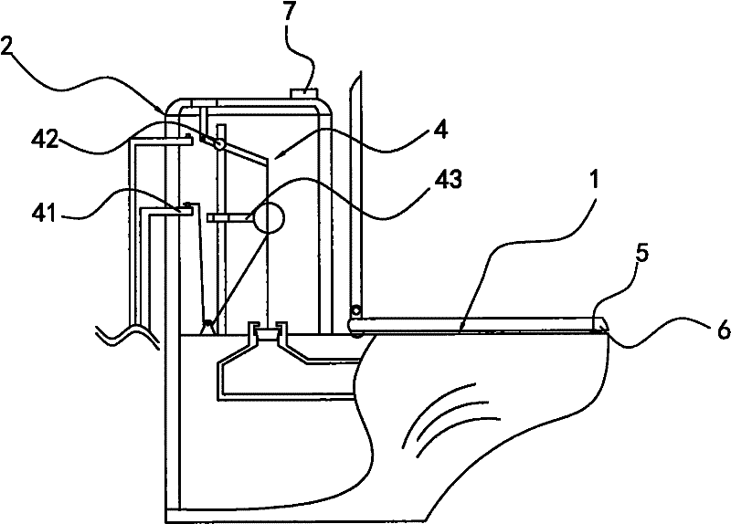
[0028] Embodiment one: if figure 1 , figure 2 As shown, the main structure of this embodiment mainly includes the toilet main body 1, the water tank 2 and the water inlet, drainage and water level control mechanism 4 in the water tank 2, and the water inlet, drainage and water level control mechanism 4 includes the water inlet mechanism 41, Drain mechanism 42 and water level control mechanism 43 three parts. A water filling switch 5 is arranged on the toilet seat 6, the water filling switch 5 is an infrared sensor switch, and a delayer 7 is connected to the water filling switch 5. The delay device 7 is controlled by the water filling switch 5 to start, and when the water filling switch 5 starts, the delay device 7 begins to record the delay time length of the flushing switch 5 starting the water filling device 41 to start filling water; when the flushing switch 5 is closed or Delay device 7 returns " zero " with the recorded delay time when disconnecting. Because some user...

Embodiment 2

[0035] Embodiment two: if figure 2 As shown, the structure of this embodiment is the same as that of Embodiment 1, the difference is that the delay time of the delayer is 4 minutes. The interval between two adjacent connections of the water filling switch 5 is less than 6 seconds, and the delayer 7 does not return to "zero".

[0036] The water storage capacity of the low water level of the water tank 2 is 35% of the high water level storage capacity.

Embodiment 3

[0037] Embodiment three: as figure 2 As shown, the structure of this embodiment is the same as that of Embodiment 1, the difference is that the delay time of the delayer is 2 minutes. The interval between two adjacent communication of the flush switch 5 is less than 8 seconds, and the delayer 7 does not return to "zero".

[0038] The water storage capacity of the low water level of the water tank 2 is 45% of the high water level storage capacity.


PUM


Abstract

The invention relates to a water level control method for a flush toilet water tank and a water saving toilet. Under the default condition, the water level in a water tank is at a low level, at that time, when the flushing is started, only a little water stored in the water tank is used for flushing the toilet. When a toilet seat is put down, the toilet carries out supplement water filling according to an original set program; and when the water level rises to a high level, the toilet stops filling water to the water tank. The toilet automatically fills water into the water tank after flushing of each time, and when the water level in the water tank reaches the low level from the zero level, the toilet pauses to fill water into the water tank. When the water tank of the toilet is in the low water level for a long time, only a small part of parts are soaked in the water, and the water pressure at the bottom of the water tank is smaller relative to that of the existing water tank. The parts of the water tank in the invention have long service life, avoid the water waste caused by the faulty operation of users, and can judge flush amount according to the type of the used toilet.

Description

technical field [0001] The utility model relates to a flush toilet and an operation method thereof, in particular to a water level control method of a flush toilet water tank and a water-saving toilet. Background technique [0002] Along with the development of society, the people's living standard and consumption demand continue to improve, and flush toilets have been popularized to the homes of many ordinary residents and various public places. Flush toilets are more comfortable to use than traditional squat toilets, but flush toilets require a large amount of water to flush the inside of the toilet to clean them; traditional flush toilets have poor water control capabilities, whether it is defecation or urination, just press When the flush water switch is turned down, all the stored water in the water tank will be flushed into the toilet. [0003] Recently, there is a flush toilet with optional flushing volume on the market. Its invention is that there are two drain valv...

Claims


Application Information

Patent Timeline
Patent Type & Authority Patents(China)
IPC IPC(8): E03D1/14E03D1/32E03D11/11
CPCY02A20/40
Inventor 倪浩
Owner 广东博士科技有限公司
Why Eureka
Try Eureka