Control handle with rotatable handle ball

A technology for manipulating handles and handles, which is used in transmission control, elements with teeth, belts/chains/gears, etc., can solve the problems of inability to meet control requirements, poor reliability, and inconvenient use of control handles, and achieve long life. , Easy to operate, reliable effect

Active Publication Date: 2010-07-14
SHANXI GUOLI INFORMATION TECH
View PDF6 Cites 2 Cited by
  • Summary
  • Abstract
  • Description
  • Claims
  • Application Information

AI Technical Summary

Problems solved by technology

[0006] In order to solve the technical problems of the existing control handles of engineering vehicles, such as inconvenient use, inability to meet control requirements, and poor reliability, the present invention provides a control handle with a rotatable handle ball head.

Method used


Image

  • Control handle with rotatable handle ball
  • Control handle with rotatable handle ball
  • Control handle with rotatable handle ball

Examples


Embodiment Construction

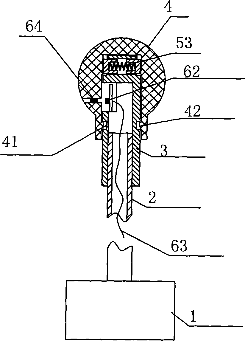
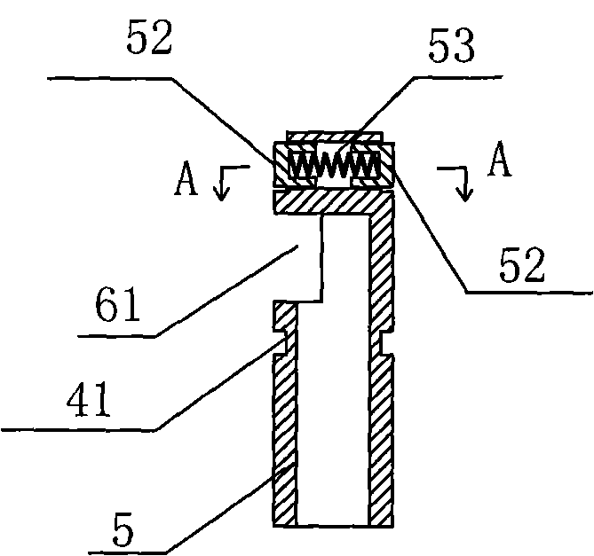
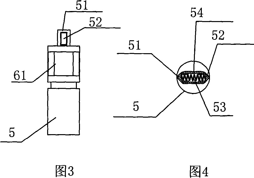
[0025] When the ball head of the handle is rotated, the magnet embedded in the upper shell rotates at the same time, and the Hall element in the handle sleeve will output the corresponding gear signal. The proper position of the handle ball (or on the instrument panel) has an indication of the rotational position of the handle ball. Because the inner end surface of the sleeve hole of the handle ball head has six gear slots and two limit ribs, the handle ball head can only rotate 150° and have only three stop positions, such as Figure 7 , Figure 8 and Figure 9 shown. The handle ball head and the handle sleeve pipe are engaged with the locking block by the locking block, so the handle ball head can only rotate axially relative to the handle sleeve pipe, but cannot move up and down. The positioning slider pushed out by the spring in the slider limit hole on the upper part of the handle sleeve can be pushed back into the slider limit hole by the smooth connection of the adja...


PUM


Abstract

The invention relates to a control handle with a rotatable handle ball, which comprises a handle seat, a hollow handle lever, a handle sleeve and a handle head, wherein the hollow handle lever extends outwards from the inside of the handle seat, and the handle sleeve and the handle head are sleeved at the upper end part of the handle lever. The invention solves the technical problems that the control handle of the current engineering vehicle can not be used conveniently, can not meet the control requirements and has poor reliability; and the invention hast the advantages of operational reliability, long service life, convenient operation and the like.

Description

technical field [0001] The invention relates to a control handle with a rotatable handle ball head, in particular to a control handle which can control different actuators and output different analog values ​​through the conversion of the handle ball head. Background technique [0002] At present, the existing engineering vehicle control handle is to install one or several key switches on the handle ball head, and to realize the conversion of the function of the control handle by pressing the switch with a finger. Although such a structure can also realize the function conversion, it is still There are the following defects: [0003] 1. This structure requires the operator to have a fixed control posture (standing or sitting operation) and a good operating environment. It is required to operate without wearing thick gloves, which is demanding and inconvenient to operate. [0004] 2. When there are many key switches (greater than two), the stroke of the key switch and the ar...

Claims


Application Information

Patent Timeline
IPC IPC(8): F16H59/10
Inventor 孙力曾卫东
Owner SHANXI GUOLI INFORMATION TECH
Why Eureka
Try Eureka