Flame stabilizer with jet injection

A technology of stable flame and deflector, applied in the direction of combustion method, combustion chamber, combustion equipment, etc., can solve the problems of restricting the thrust-to-weight ratio, and achieve the effect of good combustion scheme, weight reduction and length shortening

Inactive Publication Date: 2010-07-14
BEIHANG UNIV
View PDF0 Cites 25 Cited by
  • Summary
  • Abstract
  • Description
  • Claims
  • Application Information

AI Technical Summary

Problems solved by technology

On the one hand, the setting of afterburner greatly improves the thrust-to-weight ratio of the engine; on the other hand, it restricts the increase of the thrust-to-weight ratio

Method used


Image

  • Flame stabilizer with jet injection
  • Flame stabilizer with jet injection
  • Flame stabilizer with jet injection

Examples


Embodiment Construction

[0027] The technical solution of the present invention will be specifically described below in conjunction with the accompanying drawings and specific embodiments.

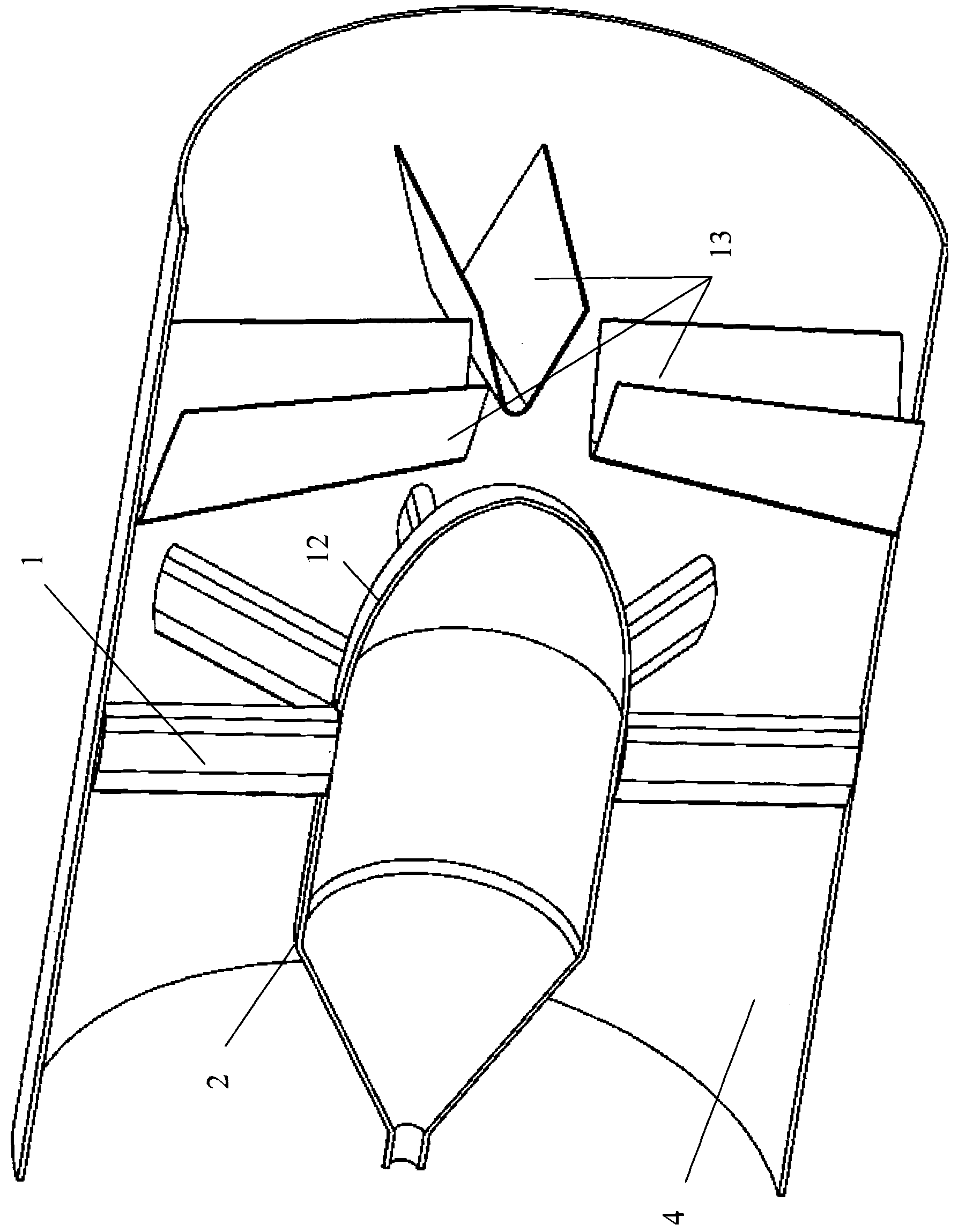
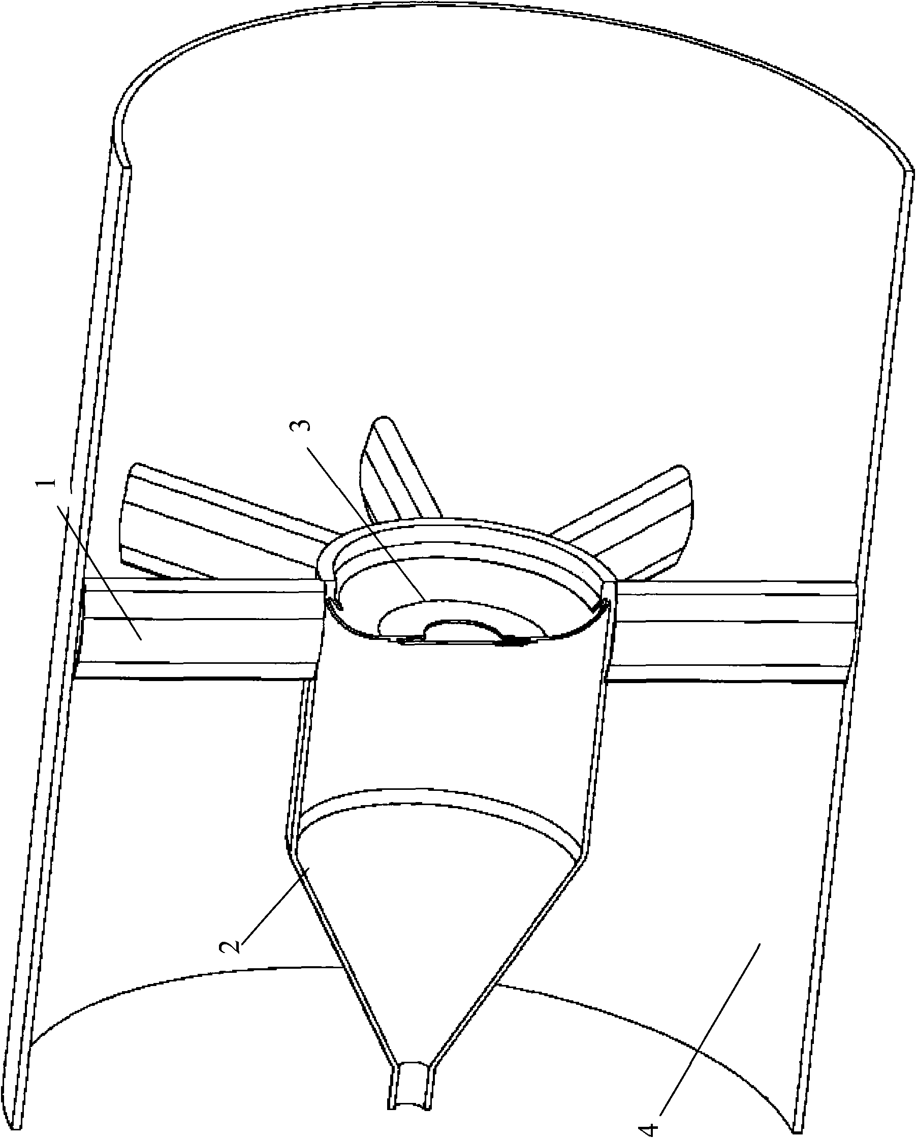
[0028] exist figure 2 In the shown embodiment of the present invention, the settings of the turbine rear frame support plate 1, the turbine rear frame inner wall 2, and the casing 4 are the same as those in the prior art, but no convex central cone and V-shaped groove flame stabilizer are provided. Instead, an inner concave curved wall 3 connected to the inner wall 2 of the turbine rear frame is provided, and the wall of the inner concave curved wall 3 is recessed in the upstream direction.

[0029] according to figure 2 In one embodiment of the present invention shown, the concave curved wall 3 is arranged near the position of the support plate 1 of the rear frame of the turbine along the axial direction of the combustion chamber.

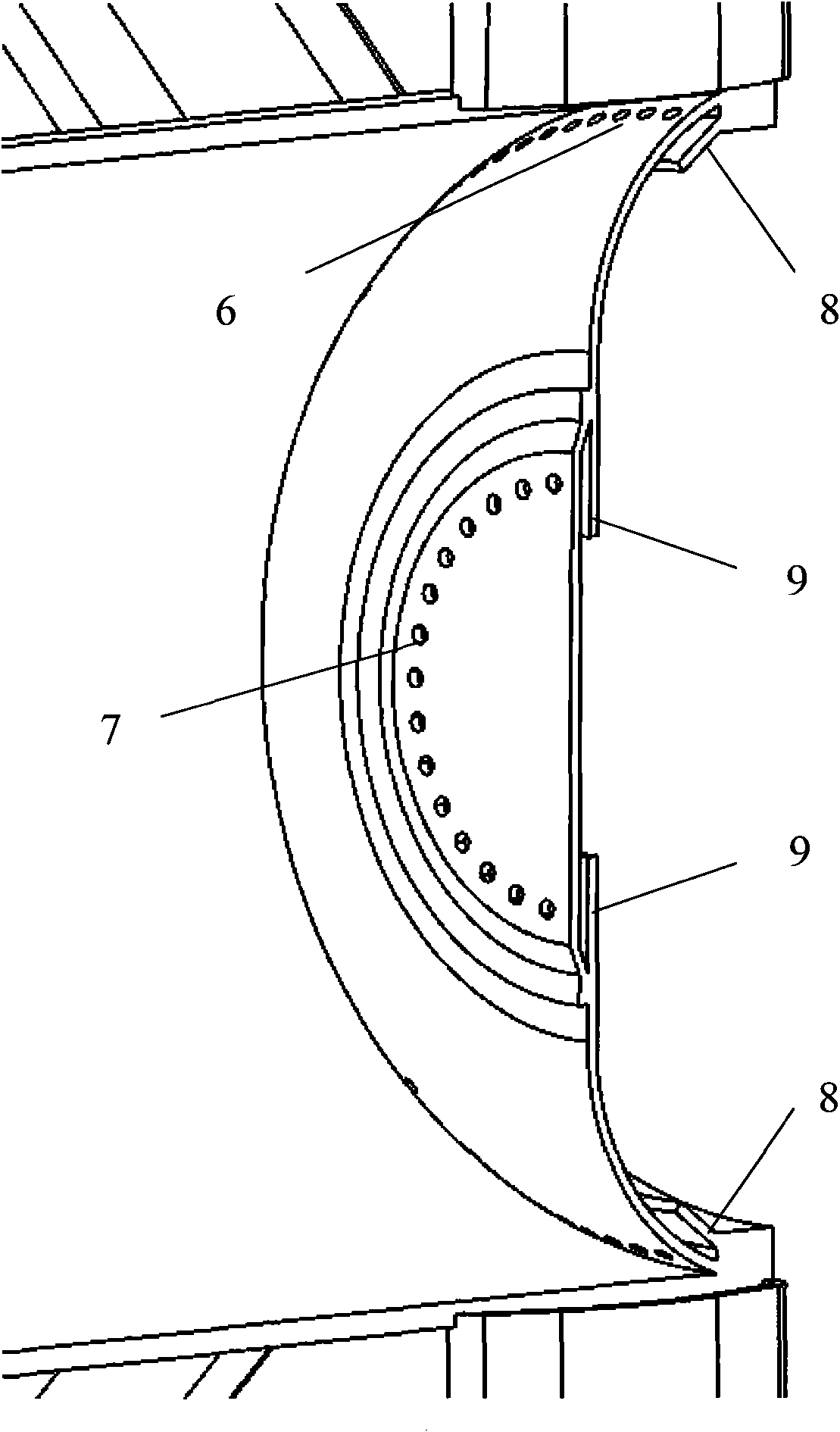
[0030] Figure 4 is indicated in figure 2 The airflow and vortex distribut...


PUM


Abstract

The invention provides a flame stabilizer for an after-combustion chamber of a gas turbine engine. In the device, which is characterized in that turbine rear frames are integrated, a radial flame stabilizer and a center cone in the prior art are omitted, and the an upstream concave structure and the a jet injection gas flow are used for forming a vortex system to form a necessary backflow region for flame stabilization, thereby reducing the amount of parts, shortening the total length of the combustion chamber, lightening the structural weight, reducing the resistance loss, and enabling the thrust-weight ratio of the engine to have great expansion lifting space.

Description

technical field [0001] The invention relates to a flame stabilizing device of an afterburner in a gas turbine engine with an afterburner, more specifically, an integrated design of a traditional afterburner turbine rear frame and a flame stabilizing device. Background technique [0002] The afterburner is an essential part of various types of fighter engines. It has been using the direct current tissue combustion scheme since its invention. figure 1 It shows a schematic cross-sectional view of a traditional flame stabilizing device with jet injection using this scheme, wherein, numeral 1 denotes the support plate of the turbine rear frame, 2 denotes the inner wall of the turbine rear frame, 4 denotes the casing, 12 denotes the central cone, and 13 denotes V-groove flame holder. In this prior art solution, such as figure 1 As shown, the center of the combustion chamber is provided with an outwardly protruding central cone 12; during work, at first the gas behind the turbine...

Claims


Application Information

Patent Timeline
Patent Type & Authority Applications(China)
IPC IPC(8): F23R3/18
Inventor 金捷季鹤鸣马梦颖马文杰王慧汝岳明
Owner BEIHANG UNIV
Why Eureka
Try Eureka