Fluid boundary control-based quantitative measurement method for fluid slippage on super-hydrophobic surface

A super-hydrophobic surface and boundary control technology, which is applied in the direction of measuring devices, surface/boundary effects, instruments, etc., can solve the problems of slip length test deviation difference, uneven cross section, and no improvement method is given, so as to improve the test Accuracy, the effect of ensuring measurement accuracy

Inactive Publication Date: 2010-07-14
JIANGSU UNIV
View PDF0 Cites 11 Cited by
  • Summary
  • Abstract
  • Description
  • Claims
  • Application Information

AI Technical Summary

Problems solved by technology

However, since the filling of the liquid in the gap between the superhydrophobic surface and the hydrophobic surface (test fixture) has a cross-sectional inhomogeneity characteristic, such as figure 2 As shown, the side appearance profile of the fluid 1 between the fixture 3 and the superhydrophobic surface 5 is not the standard drum-shaped profile required for the test, therefore, a large slip length deviation is brought about when the method of Choi is used for testing (following The slip length test deviation caused by the wettability of the superhydrophobic surface)
The Bocquet research group also questioned Choi's method in this regard. They believed that the deviation of the slip length test caused by the wettability of the superhydrophobic su...

Method used


Image

  • Fluid boundary control-based quantitative measurement method for fluid slippage on super-hydrophobic surface
  • Fluid boundary control-based quantitative measurement method for fluid slippage on super-hydrophobic surface
  • Fluid boundary control-based quantitative measurement method for fluid slippage on super-hydrophobic surface

Examples


Embodiment 1

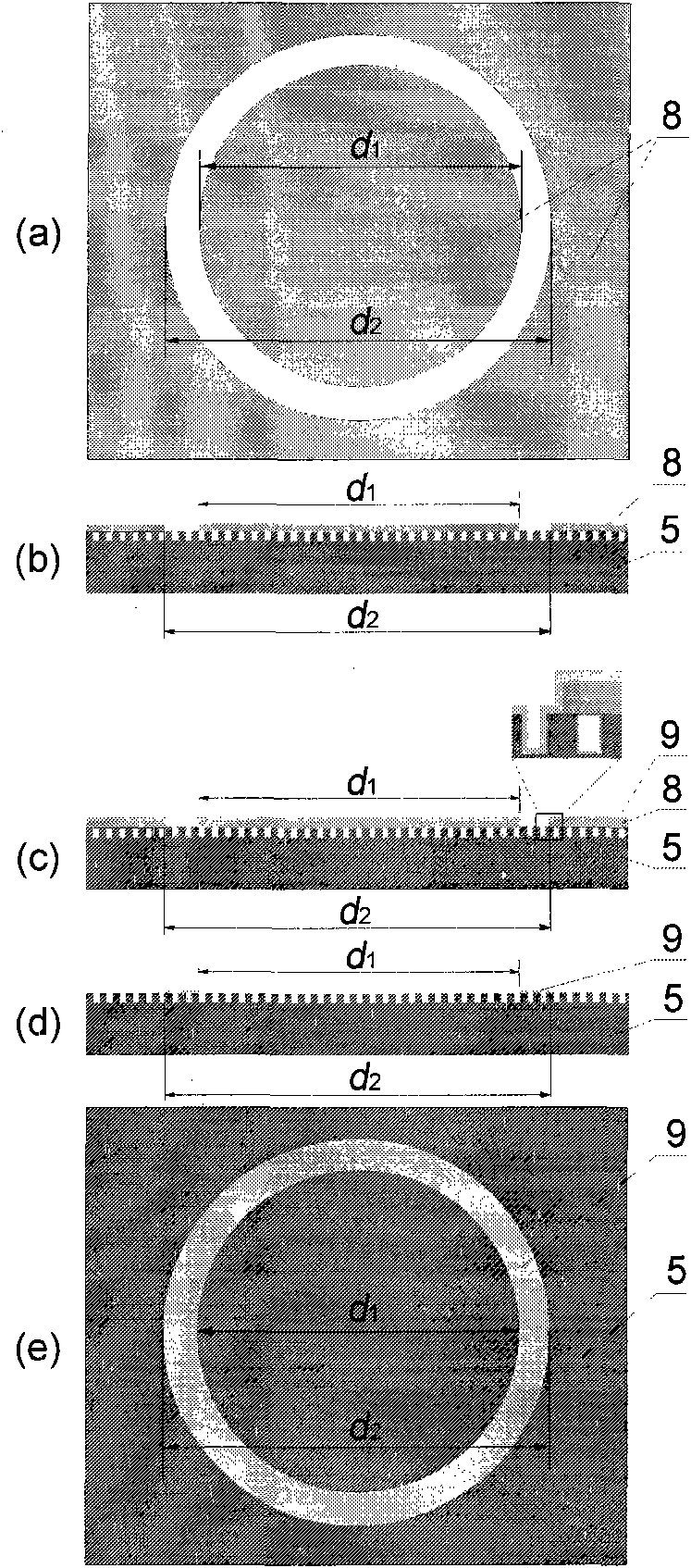
[0032] Embodiment one (using flat fixture to measure, as image 3 , Figure 4 )

[0033] image 3 Schematic diagram of the process of treating the prepared superhydrophobic surface. First process two masks 8, the diameter d of the circular mask 1 than fixture d 2 The diameter is small, the effect is better when the diameter is 1-3mm smaller, the aperture d of the circular hole mask 2 with fixture diameter d 2 Equal, no special requirements for external shape, such as image 3 (a) shown. Cover the prepared mask 8 on the superhydrophobic surface 5, such as image 3 (b) shown. Hydrophilic treatment is carried out on the superhydrophobic surface 5 covered with the mask 8, generally by spraying gold or spraying hydrophilic metal materials, and other hydrophilic coating treatment methods can also be used to perform superhydrophobic treatment after hydrophilic coating treatment. There is an extremely thin coating 9 on the surface 5 and the mask surface 8, such as image 3 ...

Embodiment 2

[0036] Embodiment two (use cone-plate fixture to measure, as image 3 , Figure 5 )

[0037] The difference from the first embodiment is that the cone-plate fixture 4 is used for measurement, and the calculation formula for the fluid slip length used is the calculation formula (4).


PUM

PropertyMeasurementUnit
Diameteraaaaaaaaaa

Abstract

The invention discloses a fluid boundary control-based quantitative measurement method for fluid slippage on a super-hydrophobic surface, which is characterized by comprising the following steps: preparing the super-hydrophobic surface, treating the prepared super-hydrophobic surface, clamping the treated super-hydrophobic surface on a rheological test platform, and calibrating the position of a clamp and mapping the clamp; and performing rheological test operation on the super-hydrophobic surface and performing rheological test operation on the fluid on a smooth hydrophobic surface under the same test condition to acquire torques applied to the clamp when the fluids are at the same shear speed under the two conditions, and calculating the slippage length according to the measured torques. The method has a wider test range, and not only can measure the length of the fluid slippage on the super-hydrophobic surface on which the super-hydrophobic area is circular and the outside of the super-hydrophobic area is the smooth hydrophobic surface, but also can measure the length of the fluid slippage on the prepared common super-hydrophobic surface.

Description

technical field [0001] The present invention relates to the technical field of fluid slippage and drag reduction on superhydrophobic surfaces, in particular to a measurement technology for fluid slippage on superhydrophobic surfaces based on fluid boundary control, which is applicable to the slippage of fluids that can be in a superhydrophobic state on superhydrophobic surfaces Length measurement and research. Background technique [0002] Due to its special super-hydrophobic effect, super-hydrophobic surfaces have received extensive attention in recent years. There have been a large number of reports on the preparation of super-hydrophobic surfaces, such as the report on super-hydrophobic surfaces by the Jiang Lei research group of the Chinese Academy of Sciences. On this basis, superhydrophobic surfaces have been gradually applied to engineering to prevent liquid adhesion and keep surfaces clean. Existing studies have shown that the unique superhydrophobic effect of super...

Claims


Application Information

Patent Timeline
IPC IPC(8): G01N13/00
Inventor 周明李健高传玉袁润李保家
Owner JIANGSU UNIV
Why Eureka
Try Eureka