Method for generating laser cutting program

A processing program, laser cutting technology, applied in the direction of program control, instrument, computer control, etc., can solve the problem of unable to extract coordinate points, achieve the effect of improving production efficiency and simplifying the operation process

Active Publication Date: 2010-07-14
GUANGDONG HANS YUEMING LASER GRP CO LTD +1
0 Cites 14 Cited by

AI-Extracted Technical Summary

Problems solved by technology

The defect of this method is that when the image outline is unclear and the boundary is not clear, the exis...

Method used

In sum, the generation method of the laser cutting processing program provided by the present invention, it adopts machine vision and digital image processing technology, human-computer interaction, generates the laser cutting processing program of high quality, and it can effectively solve ...

Abstract

The invention provides a method for generating a laser cutting program, which comprises: a step 1, acquiring digital graphic data of an object to be processed by using a camera and performing graphic pretreatment of the digital graph; step 2, manually defining a detection guide line in the pretreated digital graph, allowing a computer to extract coordinate data of graphic boundary points near the detection guide line under the guidance of the detection guide line, and forming a coordinate data link list of the coordinate data; a step 3, forming a graphic element data link list by using straight lines, arcs and parametric curve piecewise fitting coordinate data; step 4, smoothly connecting adjacent graphic elements by using a three-order Hermite parameter curve and filling the connected graphic elements into the graphic element data link list; step 5, converting the graphic element data link table into motion instruction of a laser cutter through post treatment and transmitting the motion instruction to a controller of the laser cutter to execute the motion instruction after the motion instruction is decoded. The method adopts machine vision and digital graphic processing technology to form main-machine interaction and therefore can generate a high-quality laser cutting program.

Application Domain

Technology Topic

Image

  • Method for generating laser cutting program
  • Method for generating laser cutting program
  • Method for generating laser cutting program

Examples

  • Experimental program(1)

Example Embodiment

[0027] In order to further illustrate the technical means adopted by the present invention and its decorative effects, the following describes in detail the preferred embodiments of the present invention and the accompanying drawings.
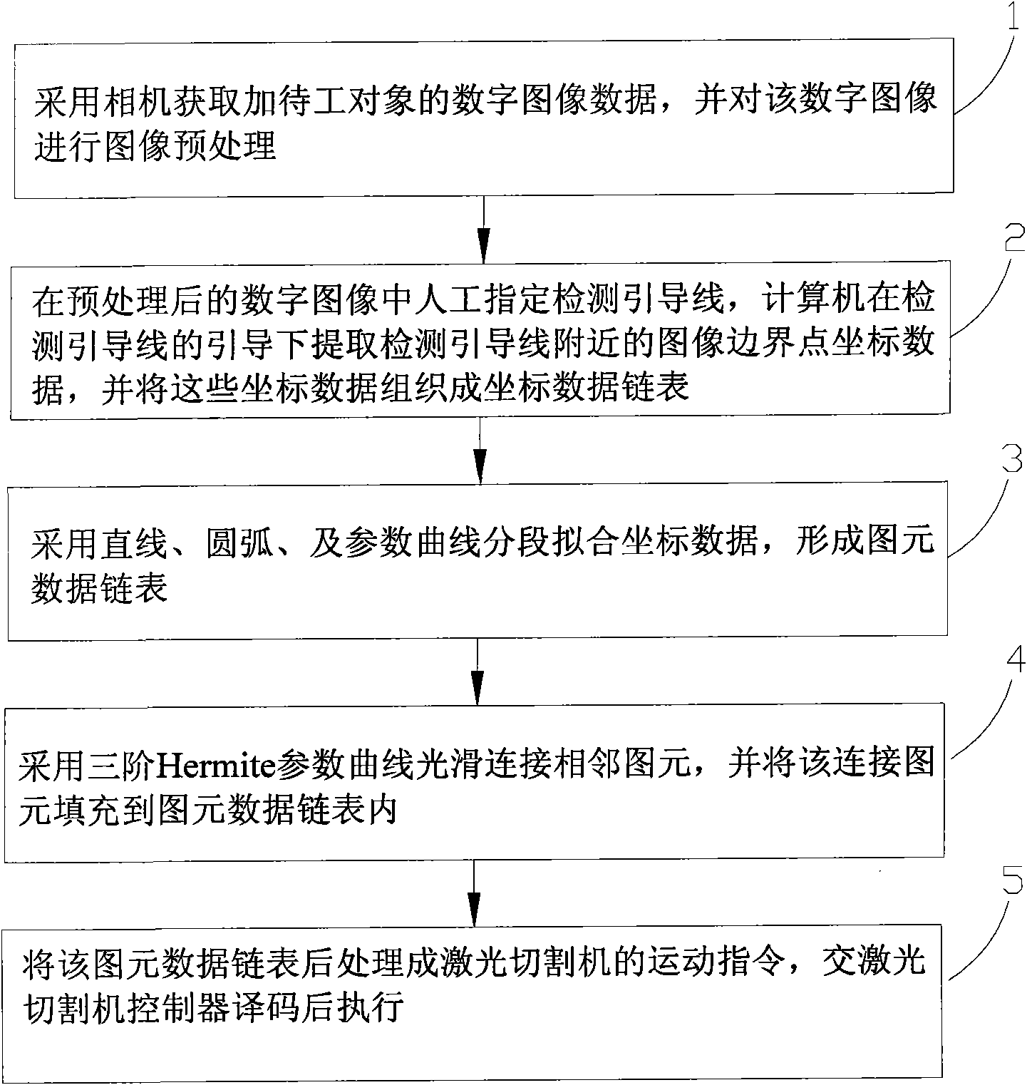
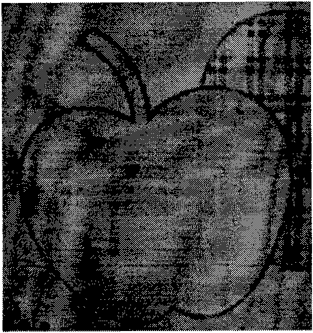
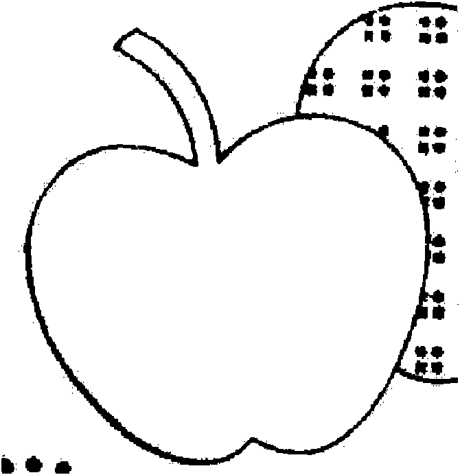
[0028] Such as figure 1 As shown, the present invention provides a method for generating a laser cutting processing program, which includes: Step 1. Use a camera to acquire digital image data of an object to be processed, and perform image preprocessing on the digital image. The image preprocessing includes image filtering or image enhancement. The image filtering includes threshold filtering. For different digital images, different filtering methods can be used to make the image easier to process. figure 2 Shown is the original digital image of an embodiment of the object to be processed in the present invention. image 3 It is the digital image after threshold filtering in step 1.
[0029] Step 2. Manually specify the detection guide line in the preprocessed digital image. Under the guidance of the detection guide line, the computer extracts the coordinate data of the image boundary points near the detection guide line, and organizes these coordinate data into a coordinate data linked list. Such as Figure 4 As shown, the detection guide line is manually drawn near the outline of the digital image after preprocessing, and the computer generates the detection line at equal intervals on the detection guide line, and the interval distance is preset by the system. On the detection line, generate equidistant detection points according to the value preset by the system, project the corresponding 3X3 pixels on the detection point to the detection point according to the rectangular interpolation method, and calculate the pixel difference of the detection point along the detection line, and at the peak of the difference Can be judged as a boundary. Finally, the point coordinate data on the boundary is organized into a coordinate data linked list according to the numerical control linked list for storage.
[0030] Step 3. Use straight lines, arcs, and parameter curves to fit the coordinate data in sections to form a linked list of primitive data. Such as Figure 5 As shown, the boundary point coordinates extracted on the boundary contour are segmented and fitted into a straight line segment, an arc, and a parametric curve.
[0031] Step 4. Use the third-order Hermite parameter curve to smoothly connect adjacent graphic elements, and fill the connected graphic elements into the graphic element data linked list. Such as Image 6 As shown, it is a partial schematic diagram of using third-order Hermite interpolation to construct a smooth transition curve at the interval between adjacent primitives. Figure 7 That is, the motion trajectory diagram generated by using the smooth transition to withdraw money.
[0032] Step 5: Post-process the linked list of graphic element data into the motion instructions of the laser cutting machine, which will be decoded and executed by the laser cutting machine controller. will Figure 7 After the motion trajectory map generated in the post-processing to hide the image information, it can be as Picture 8 As shown in the motion trajectory diagram, the motion trajectory is processed into the motion instruction of the laser cutting machine, which can be decoded by the laser cutting machine controller.
[0033] In summary, the method for generating laser cutting processing programs provided by the present invention uses machine vision and digital image processing technology, human-computer interaction, to generate high-quality laser cutting processing programs, which can effectively solve the problem of unclear or unclear image contours. When the boundary is not clear, the artificial outline is drawn intelligently and the coordinate points cannot be extracted from the image outline, which greatly simplifies the operation process and improves the production efficiency.
[0034] As mentioned above, for those of ordinary skill in the art, various other corresponding changes and modifications can be made according to the technical solutions and technical ideas of the present invention, and all these changes and modifications shall belong to the appended claims of the present invention. The scope of protection.

PUM

no PUM

Description & Claims & Application Information

We can also present the details of the Description, Claims and Application information to help users get a comprehensive understanding of the technical details of the patent, such as background art, summary of invention, brief description of drawings, description of embodiments, and other original content. On the other hand, users can also determine the specific scope of protection of the technology through the list of claims; as well as understand the changes in the life cycle of the technology with the presentation of the patent timeline. Login to view more.

Similar technology patents

Intelligent equipment control method and device

Owner:BEIJING XIAOMI MOBILE SOFTWARE CO LTD

Classification and recommendation of technical efficacy words

  • Simplify the operation process
  • Increase productivity

Multimedia file search method and device

Owner:BEIJING SOGOU TECHNOLOGY DEVELOPMENT CO LTD

Preparation method for nano-microcrystalline cellulose

ActiveCN104293858AReduce the amount of acid usedSimplify the operation processFermentationAlgluceraseGlucanase
Owner:TIANJIN UNIVERSITY OF SCIENCE AND TECHNOLOGY

Method and system to define implement and enforce workflow of a mobile workforce

ActiveUS20130090969A1Improves work force capabilityIncrease productivityResourcesWorkflow processWorkflow
Owner:HYPHEN SOLUTIONS LLC

Apparati, methods, and compositions for universal microbial diagnosis, detection, quantification, and specimen-targeted therapy

InactiveUS20120129794A1Increase productivityAccurate and rapid and sensitive microbial diagnosis and detection and quantificationAntibacterial agentsBiocidePopulationMolecular Targeted Therapies
Owner:DOWD SCOT E +2
Why Eureka
Try Eureka