
A parallel plate magnetic capacitor

A technology of capacitors and parallel plates, applied in the field of electric energy storage devices

Inactive Publication Date: 2010-07-14
NORTHERN LIGHTS SEMICON
View PDF3 Cites 2 Cited by
  • Summary
  • Abstract
  • Description
  • Claims
  • Application Information

AI Technical Summary

Problems solved by technology

Therefore, a trade-off must be made between the capacitance value and the capacitor size, otherwise there will be a bottleneck in increasing the capacitance value while maintaining the same capacitor size

Method used


Image

  • A parallel plate magnetic capacitor
  • A parallel plate magnetic capacitor
  • A parallel plate magnetic capacitor

Examples


Embodiment Construction

[0034] It is to be understood that the following descriptions are intended to provide various embodiments by which various features of the invention may be implemented. The following descriptions of specific embodiments of components and configurations are used to simplify the description of the present invention, which are of course only illustrative and not limiting.

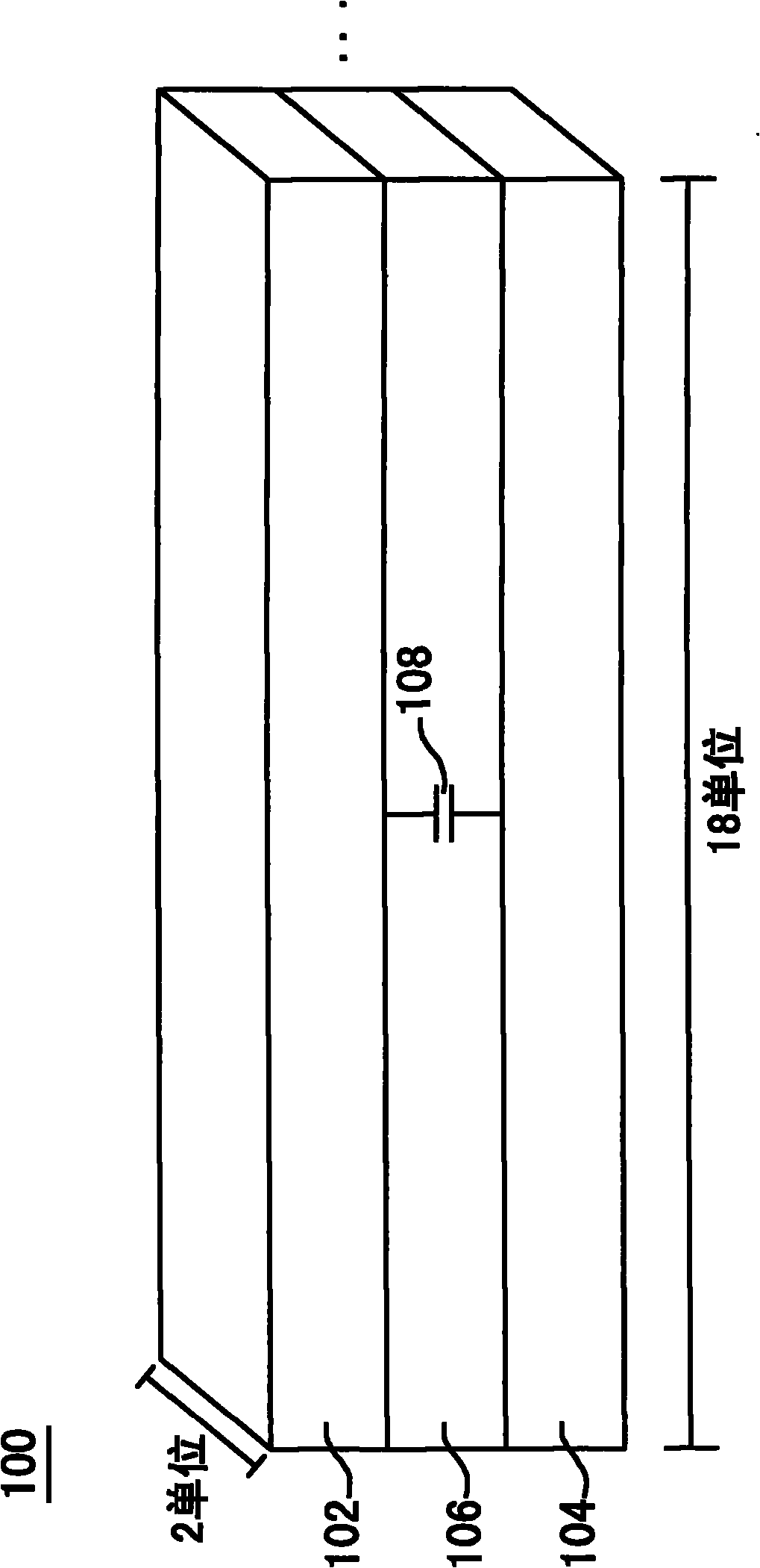
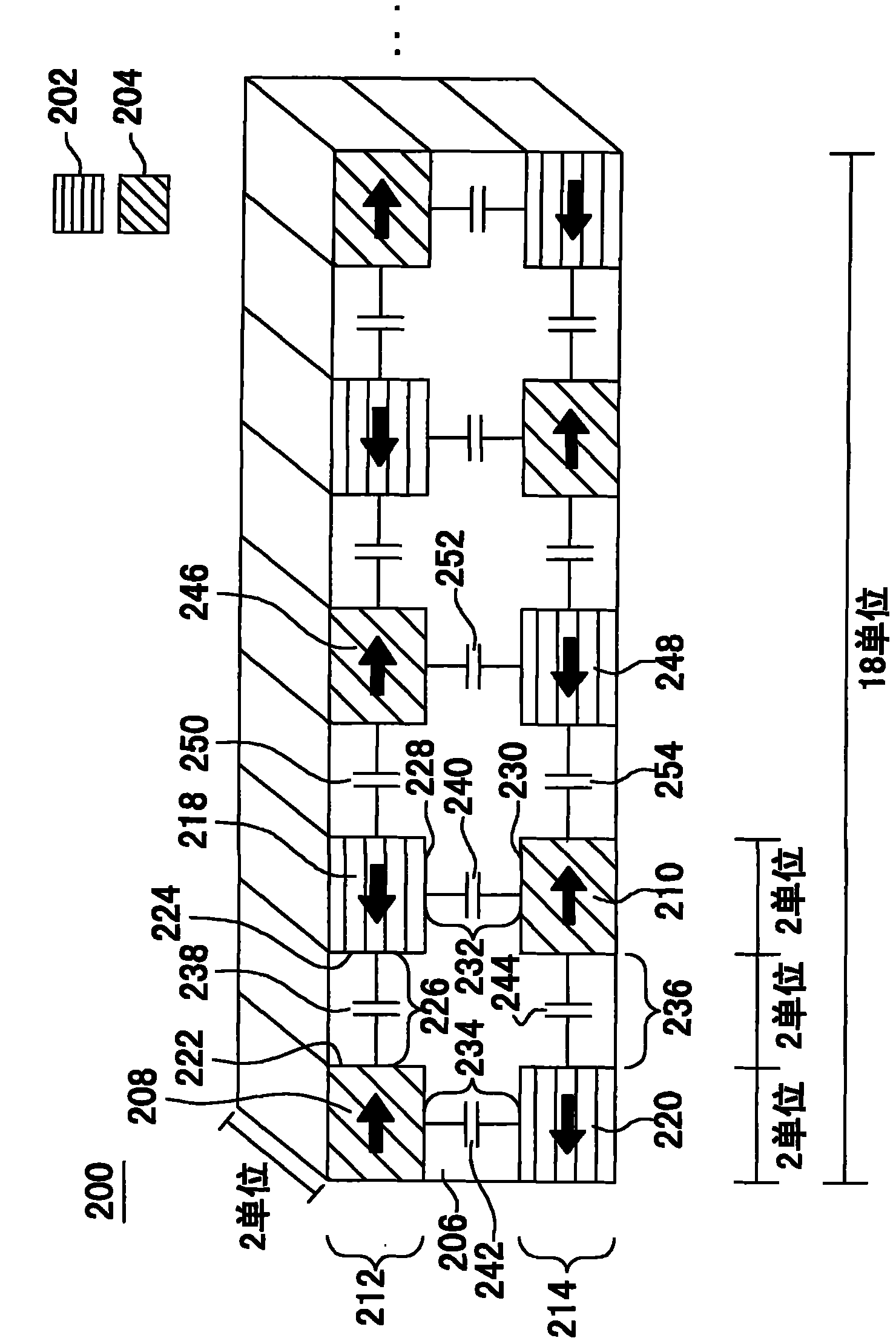
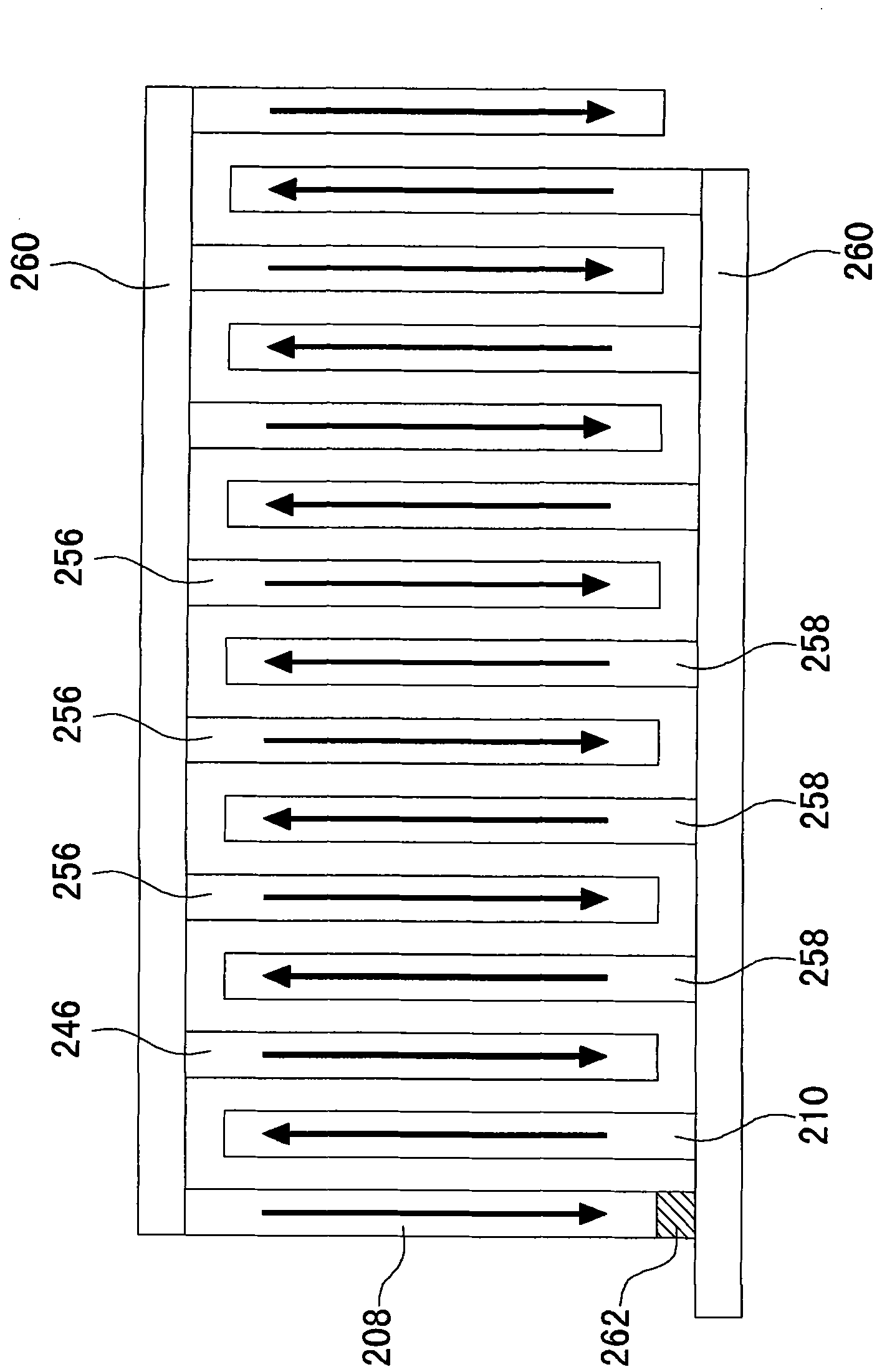
[0035] Please refer to figure 2 , which shows a cross-sectional view of a parallel-plate magnetic capacitor according to an embodiment of the present invention. A magnetic capacitor 200 includes: a first conductive magnetic metal 202, a second conductive magnetic metal 204 and a dielectric layer 206, wherein the first conductive magnetic metal 202 has a first upper finger structure 208 located on the upper plane 212, and a first lower finger The finger structure 210 is located on the lower plane 214, and the first upper finger structure 208 is electrically connected to the first lower finger structure 210, w...


PUM


Abstract

A plurality of parallel plate capacitors comprise a first conductive material having a first upper finger located on an upper plane and a first lower finger located on a lower plane. The capacitor also includes a second conductive material having a second upper finger and a second lower finger, the second upper finger located on the upper plane such that the second upper finger is next to the first upper finger forming a first interface and on top of the first lower finger forming a second interface, the second lower finger located on the lower plane such that the second lower finger is next to the first lower finger forming a third interface and below the first upper finger forming a fourth interface. The capacitor includes a dielectric material located in the first interface, the secondinterface, the third interface, and the fourth interface.

Description

technical field [0001] The present invention relates to an electrical energy storage device, and more particularly to a parallel plate magnetic capacitor device. Background technique [0002] Generally speaking, the structure of a parallel plate capacitor is composed of two parallel metal plates and an insulating material in the middle. The calculation of the capacitance value can be expressed by formula (1), and the energy corresponding to the capacitance value can be expressed by formula (2): [0003] C = e 0 e k A r - - - ( 1 ) [0004] E=(1 / 2)CV 2 (2) [0005] Among them, C represents the capacitance value of the parallel plate capacitor, e 0 represents the dielectric constant in vacuum, e k Represents the relative pe...

Claims


Application Information

Patent Timeline
IPC IPC(8): H01G4/00H01G4/38
CPCH01G4/008H01G4/30H01G4/38H01G4/385
Inventor 赖锜
Owner NORTHERN LIGHTS SEMICON
Learn More