Control circuit of switching tube

A technology of control circuit and switch tube, which is applied in the direction of conversion equipment without intermediate conversion to AC, can solve the problems of slow turn-on speed of the switch tube and the switch tube cannot be fully turned on, and achieves the improvement of forward conduction voltage, simple structure and convenience. effect achieved

Inactive Publication Date: 2010-07-14
SICHUAN COC DISPLAY DEVICES
View PDF0 Cites 0 Cited by
  • Summary
  • Abstract
  • Description
  • Claims
  • Application Information

AI Technical Summary

Problems solved by technology

[0008] The purpose of the present invention is to provide a control circuit for a switch tube, which can solve the problems in the related art that the switch tube is turned on at a relatively slow speed, and the switch tube cannot be completely turned on.

Method used


Image

  • Control circuit of switching tube
  • Control circuit of switching tube
  • Control circuit of switching tube

Examples


Embodiment Construction

[0021] The present invention will be described in detail below with reference to the accompanying drawings and in combination with embodiments.

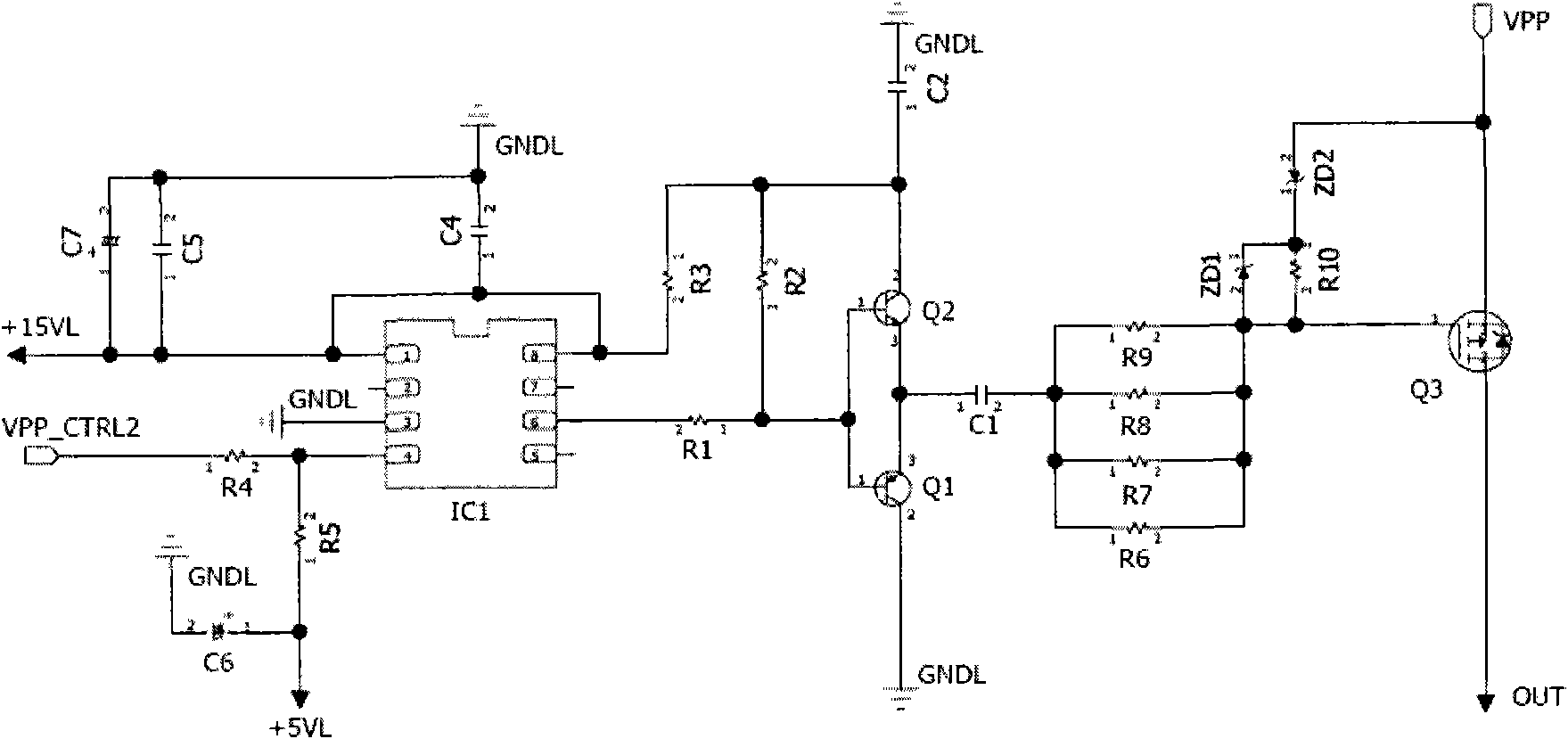
[0022] image 3 is a schematic diagram of a control circuit of a switching tube according to an embodiment of the present invention. Such as image 3 As shown, the control circuit of the switching tube includes: a waveform generating circuit, a DC blocking capacitor C1, current limiting resistors R6~R9, a voltage stabilizing tube ZD1 and a resistor R10 as the first voltage stabilizing component, and a second voltage stabilizing component Regulator tube ZD2, and switch tube Q3.

[0023] In the control circuit of the above-mentioned switching tube, the waveform generating circuit includes: a level conversion circuit composed of a level conversion chip IC1 and its peripheral circuits, which is used to convert the input low-voltage waveform signal into a 15V level waveform output; and, A push-pull circuit composed of transistors Q1 an...


PUM


Abstract

The invention provides a control circuit of a switching tube, which comprises a waveform generating circuit, a stopping direct current voltage capacitor and the switching tube, wherein the first end of the stopping direct current voltage capacitor is connected to the waveform generating circuit, the second end of the stopping direct current voltage capacitor is connected to a grid of the switching tube, a source of the switching tube is connected to a power supply voltage, and a drain of the switching tube is an output end. Moreover, the control circuit of the switching tube also comprises a first voltage stabilizing component and a second voltage stabilizing component, wherein the first end of the first voltage stabilizing component is connected to the second end of the stopping direct current voltage capacitor and the grid of the switching tube, the second end of the first voltage stabilizing component is connected to the first end of the second voltage stabilizing component, and the second end of the second voltage stabilizing component is connected to the source of the switching tube. The control circuit of the switching tube achieves the effect that a voltage switching circuit has strong interference rejection.

Description

technical field [0001] The invention relates to a control circuit of a switch tube. Background technique [0002] In the working process of PDP (Plasma Display Panel, Plasma Display Panel), considering the recycling of energy, the power supply of the address electrodes needs to cooperate with the energy recovery circuit, wherein the voltage is provided to the address electrodes in the form of switches. A common practice is to use a power switch tube in the circuit to realize the switching on and off of the voltage. [0003] figure 1 is a schematic diagram of a voltage switch circuit according to the related art. Such as figure 1 As shown, the waveform generating circuit is connected with the switch tube Q1, and is used to output the waveform signal to Q1, so as to realize switch control. In addition, the power supply voltage VPP is the power supply for the address electrodes required by the chip on the TCP (Tape Carrier Package, flexible wiring of the packaged chip), and...

Claims


Application Information

Patent Timeline
Patent Type & Authority Applications(China)
IPC IPC(8): H02M3/07
Inventor 陆得盛
Owner SICHUAN COC DISPLAY DEVICES
Why Eureka
Try Eureka