Control circuit of switching tube
A technology of control circuit and switch tube, which is applied in the direction of conversion equipment without intermediate conversion to AC, can solve the problems of slow turn-on speed of the switch tube, and the switch tube cannot be fully turned on, so as to improve the forward conduction voltage, simple structure, strong The effect of anti-interference ability
- Summary
- Abstract
- Description
- Claims
- Application Information
AI Technical Summary
Problems solved by technology
Method used
Image
Examples
Embodiment Construction
[0021] The present invention will be described in detail below with reference to the accompanying drawings and in combination with embodiments.
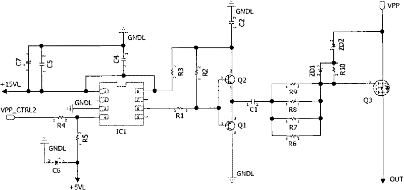
[0022] image 3 is a schematic diagram of a control circuit of a switching tube according to an embodiment of the present invention. like image 3 As shown, the control circuit of the switching tube includes: a waveform generating circuit, a DC blocking capacitor C1, current limiting resistors R6~R9, a voltage stabilizing tube ZD1 and a resistor R10 as the first voltage stabilizing component, and a second voltage stabilizing component Regulator tube ZD2, and switch tube Q3.
[0023] In the control circuit of the above-mentioned switching tube, the waveform generating circuit includes: a level conversion circuit composed of a level conversion chip IC1 and its peripheral circuits, which is used to convert the input low-voltage waveform signal into a 15V level waveform output; and, A push-pull circuit composed of transistors Q1 and Q...
PUM
 Abstract
Description
Claims
Application Information
 - R&D
- Intellectual Property
- Life Sciences
- Materials
- Tech Scout
- Unparalleled Data Quality
- Higher Quality Content
- 60% Fewer Hallucinations
Browse by: Latest US Patents, China's latest patents, Technical Efficacy Thesaurus, Application Domain, Technology Topic, Popular Technical Reports.
© 2025 PatSnap. All rights reserved.Legal|Privacy policy|Modern Slavery Act Transparency Statement|Sitemap|About US| Contact US: help@patsnap.com


