Method and system for realizing commutation of high-voltage direct-current transmission converter valve
A high-voltage direct current transmission and system realization technology, applied in the direction of AC network circuits, electrical components, circuit devices, etc., can solve problems such as weak resistance, avoid failure, speed up commutation, and improve commutation reliability.
- Summary
- Abstract
- Description
- Claims
- Application Information
AI Technical Summary
Problems solved by technology
Method used
Image
Examples
Embodiment 1
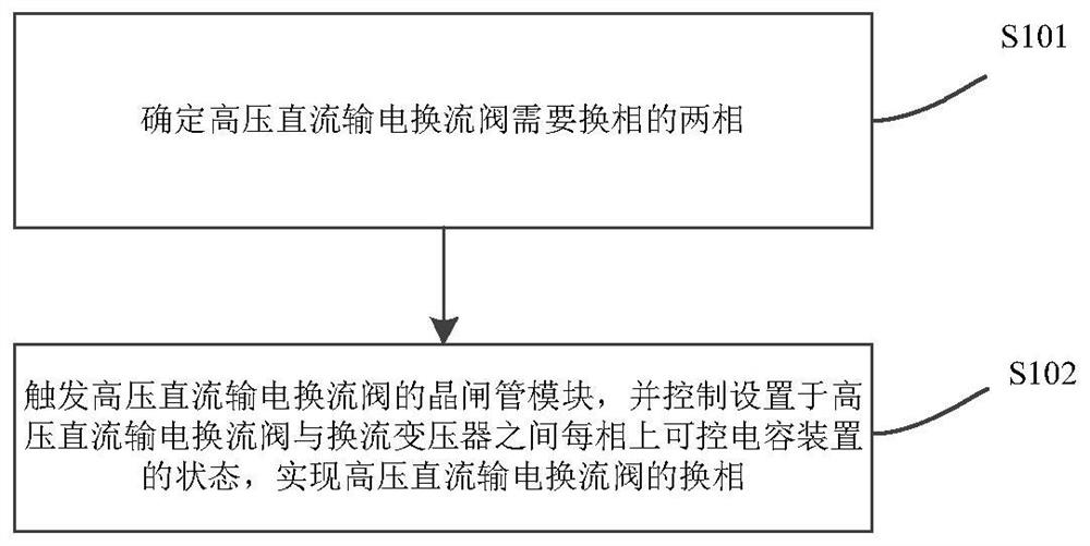
[0050] Embodiment 1 of the present invention provides a method for implementing commutation of HVDC converter valves, the specific flow chart is as follows figure 1 As shown, the specific process is as follows:
[0051] S101: Determine the two phases that need to be commutated by the HVDC converter valve, specifically, determine the two phases that need to be commutated by the HVDC converter valve according to the AC voltage measurement of the HVDC converter valve;
[0052] S102: Trigger the thyristor module of the HVDC converter valve, and control the state of the controllable capacitor device on each phase between the HVDC converter valve and the converter transformer, so as to realize the phase commutation of the HVDC converter valve.
[0053] The phase commutation of the HVDC converter valve is realized by controlling the state of the controllable capacitor device, which is specifically divided into three situations: 1) The phase commutation of the HVDC converter valve fro...
Embodiment 2
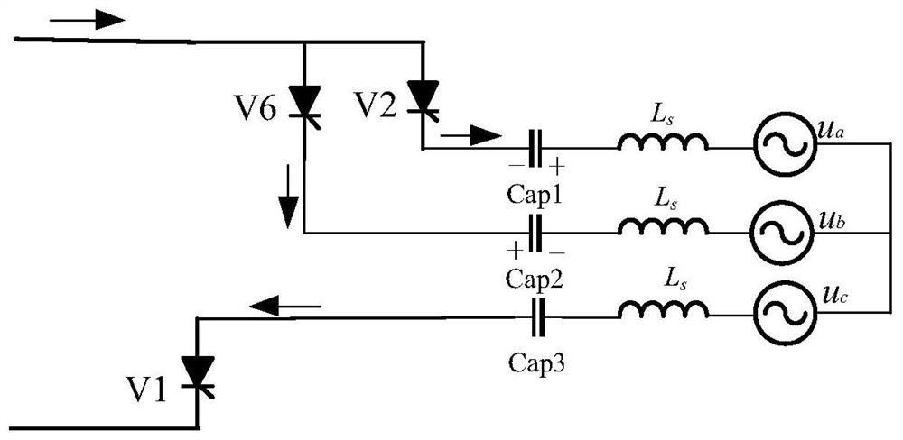
[0068] Based on the same inventive concept, Embodiment 2 of the present invention also provides a system for implementing commutation of HVDC converter valves, such as Figure 6 as shown, Figure 6 Among them, T is the converter transformer, S is the three-phase AC power supply, Cap1 is the controllable capacitor device installed on the HVDC converter valve and converter transformer phase A, and Cap2 is the HVDC converter valve and converter transformer B phase The controllable capacitor device is set on the upper side, Cap3 is the controllable capacitor device on the HVDC converter valve and the C phase of the converter transformer, V1-V6 is the thyristor module on each bridge arm of the HVDC converter valve, v d is the DC side voltage of the HVDC converter valve.
[0069] The HVDC converter valve phase commutation implementation device provided in Embodiment 2 of the present invention includes a HVDC converter valve, a controllable capacitor device, and a converter transfor...
PUM
 Abstract
Description
Claims
Application Information
 - R&D
- Intellectual Property
- Life Sciences
- Materials
- Tech Scout
- Unparalleled Data Quality
- Higher Quality Content
- 60% Fewer Hallucinations
Browse by: Latest US Patents, China's latest patents, Technical Efficacy Thesaurus, Application Domain, Technology Topic, Popular Technical Reports.
© 2025 PatSnap. All rights reserved.Legal|Privacy policy|Modern Slavery Act Transparency Statement|Sitemap|About US| Contact US: help@patsnap.com


