Schottky Barrier Diodes
A Schottky potential and diode technology, applied in semiconductor devices, electrical components, circuits, etc., can solve problems such as increased contact resistance and forward voltage
- Summary
- Abstract
- Description
- Claims
- Application Information
AI Technical Summary
Problems solved by technology
Method used
Image
Examples
Embodiment 1
[0059] Next, more specific examples of the present invention will be described.
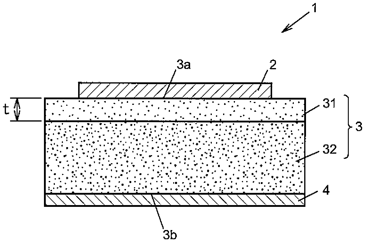
[0060] In this example, β-Ga 2 o 3 substrate as n + semiconductor layer 32 . In the β-Ga 2 o 3 substrate, doped with Si as a dopant, and formed with an electron carrier concentration of 1×10 19 cm -3 . In addition, the plane direction of the substrate was formed to be (010). Although the plane direction of the substrate is not particularly limited, it is preferably a plane rotated by an angle of 50° to 90° from the (100) plane. For example, there are (010) plane, (001) plane, (−201) plane, (101) plane, and (310) plane. In this way, re-evaporation from the substrate during epitaxial growth can be suppressed, and the growth rate can be increased. In addition, it may be a surface obtained by rotating the direction of the substrate surface by an angle of 37.5° or less from the (010) plane. In this case, it is possible to make n + Semiconductor layer 32 and n - The interface of the semico...
Deformed example 1
[0071] Figure 6A as well as Figure 6B A Schottky diode 1A showing a first modified example of the embodiment of the present invention, in which Figure 6A is a top view, Figure 6B yes Figure 6A A-A cutaway view.
[0072] The Schottky diode 1A has a quadrangular shape in plan view, and a Schottky electrode layer 2 having a similar quadrangular shape is formed at the center thereof. In addition, the Schottky diode 1A includes an n-type semiconductor layer 3, and the n-type semiconductor layer 3 has an n-type semiconductor layer with a low electron carrier concentration. - The semiconductor layer 31, and having a ratio of the n - The n of the high electron carrier concentration of the high electron carrier concentration of the semiconductor layer 31 + semiconductor layer 32 . n for low electron carrier concentration - The semiconductor layer 31 is formed on the side of the n-type semiconductor layer 3 that is in Schottky contact with the Schottky electrode layer 2 . ...
Deformed example 2
[0077] Figure 7A as well as Figure 7B A Schottky diode 1B showing a second modified example of the embodiment of the present invention, in which Figure 7A is a top view, Figure 7B yes Figure 7A A-A cutaway view.
[0078] For Schottky diode 1B, at n - The structure in which the resistive layer 310 is formed on a part of the semiconductor layer 31 is different from the Schottky diode 1A, and the other structures are the same as the Schottky diode 1A. from n - The resistive layer 310 is formed on the upper surface 31 a side of the semiconductor layer 31 from the portion in contact with the peripheral portion of the Schottky electrode layer 2 to the side surface 31 b. The resistive layer 310 at n + Formed on the semiconductor layer 32 are n -Afterwards, the semiconductor layer 31 can be formed, for example, by annealing in an oxygen atmosphere. In addition, this region may be formed as a P-type layer instead of the resistance layer 310 .
[0079] According to the Sc...
PUM
 Abstract
Description
Claims
Application Information
 - R&D
- Intellectual Property
- Life Sciences
- Materials
- Tech Scout
- Unparalleled Data Quality
- Higher Quality Content
- 60% Fewer Hallucinations
Browse by: Latest US Patents, China's latest patents, Technical Efficacy Thesaurus, Application Domain, Technology Topic, Popular Technical Reports.
© 2025 PatSnap. All rights reserved.Legal|Privacy policy|Modern Slavery Act Transparency Statement|Sitemap|About US| Contact US: help@patsnap.com


