Supercharge Your Innovation With Domain-Expert AI Agents!

Device and method for choosing transmission path in wireless network

A transmission path and wireless network technology, applied in the field of wireless networks, can solve the problems of not being able to obtain the benefits of multiple antennas, differences in antenna gain values, and low signal strength

Active Publication Date: 2010-07-14
REALTEK SEMICON CORP
View PDF0 Cites 5 Cited by
  • Summary
  • Abstract
  • Description
  • Claims
  • Application Information

AI Technical Summary

Problems solved by technology

[0004] The first example, in a wireless network, since the signal is transmitted in the air, the transmission of the signal is easily affected by the wireless channel, such as: multipath (multipath), fading (fading), mobility, etc., may cause Signal strengths received by multiple transceiver antennas are different from each other
[0005] In the second example, the conditions of the antenna module itself are different. For example, different antennas are used for different receiving paths, resulting in differences in the gain value of the antenna itself.
[0006] When the signal strength between the antennas is different (for example: the difference is too large), not only the benefits brought by multiple antennas cannot be obtained, but also because the signal strength of one antenna is too low, the receiving ability of other antennas will be affected, resulting in Overall data throughput is reduced

Method used


Image

  • Device and method for choosing transmission path in wireless network
  • Device and method for choosing transmission path in wireless network
  • Device and method for choosing transmission path in wireless network

Examples


Embodiment Construction

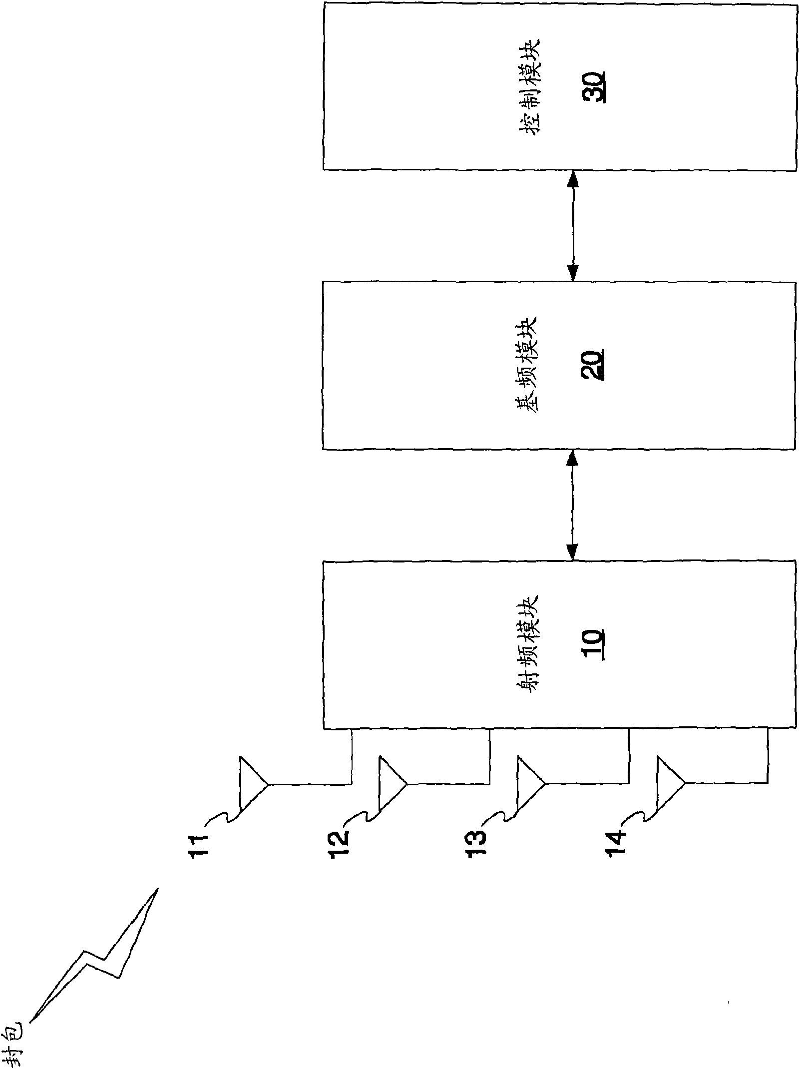
[0021] Please refer to" figure 1 ", the figure shows a schematic diagram of the first embodiment of the transmission path selection device in a wireless network. The transmission path selection device proposed by the present invention includes: a radio frequency module 10, a baseband module 20, and a control module 30.

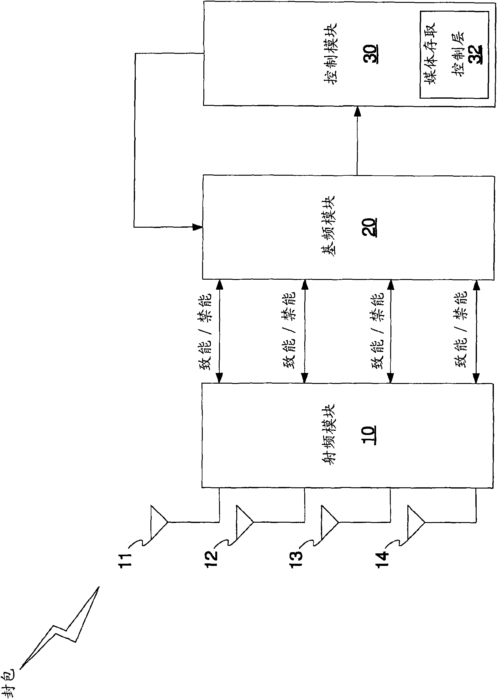
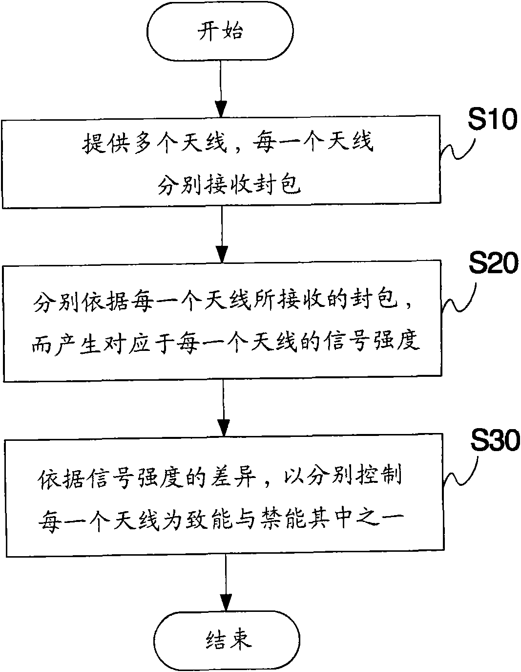
[0022] The radio frequency (RF) module 10 is coupled to multiple antennas, such as " figure 1 "There are four antennas 11-14 shown, and each antenna receives a packet respectively. The number of antennas can be set according to requirements, and is not limited thereto. The base band (BB) module 20 respectively demodulates (de-modulates) the packets received by each antenna 11-14 to generate a signal strength (SS) corresponding to each antenna 11-14.

[0023] The control module 30 controls the antenna to be enabled or disabled according to the signal strength of each antenna 11-14. With " figure 1 In the embodiment, the radio frequency module 10 has four antennas 1...


PUM


Abstract

The invention relates to a device for choosing a transmission path in a wireless network, comprising a radio frequency module, a fundamental frequency module and a control module. The radio frequency module is coupled with multiple antennas and is used for processing packets respectively received by the antennas. The fundamental frequency module generates signal strength corresponding to the antennas according to the packets received by each antenna. The control module is coupled with the fundamental frequency module for receiving signal strength and respectively controls the antennas to be either enabled or disabled according to signal strength difference.

Description

Technical field [0001] The invention relates to a wireless network, in particular to a transmission path selection device and method in the wireless network. Background technique [0002] In a wireless network (wireless network) system, having multiple transceiver antennas can bring many benefits, such as increasing reception stability and improving data throughput (TP). Therefore, the multi-input multi-output (MIMO) technology composed of multiple antennas has been widely used in wireless network systems. [0003] Under the multiple input and output mechanism, the signal strength (SS) difference between multiple transmitting and receiving antennas is likely to be too large, such as: [0004] In the first example, in a wireless network, because the signal is transmitted in the air, the signal transmission is easily affected by the wireless channel, such as: multipath (multipath), attenuation (fading), mobility (mobility), etc., may cause The signal strengths received by multiple tr...

Claims


Application Information

Patent Timeline
IPC IPC(8): H04W40/02H04W84/18
CPCY02D30/70
Inventor 张仲尧
Owner REALTEK SEMICON CORP
Features
  • R&D
  • Intellectual Property
  • Life Sciences
  • Materials
  • Tech Scout
  • Unparalleled Data Quality
  • Higher Quality Content
  • 60% Fewer Hallucinations
Learn More