Electronic mirror device
An electronic mirror and image technology, applied in TV, color TV, electrical components, etc., can solve problems such as difficult work, achieve the effect of reducing burden and reducing sense of incongruity
- Summary
- Abstract
- Description
- Claims
- Application Information
AI Technical Summary
Problems solved by technology
Method used
Image
Examples
Embodiment 1
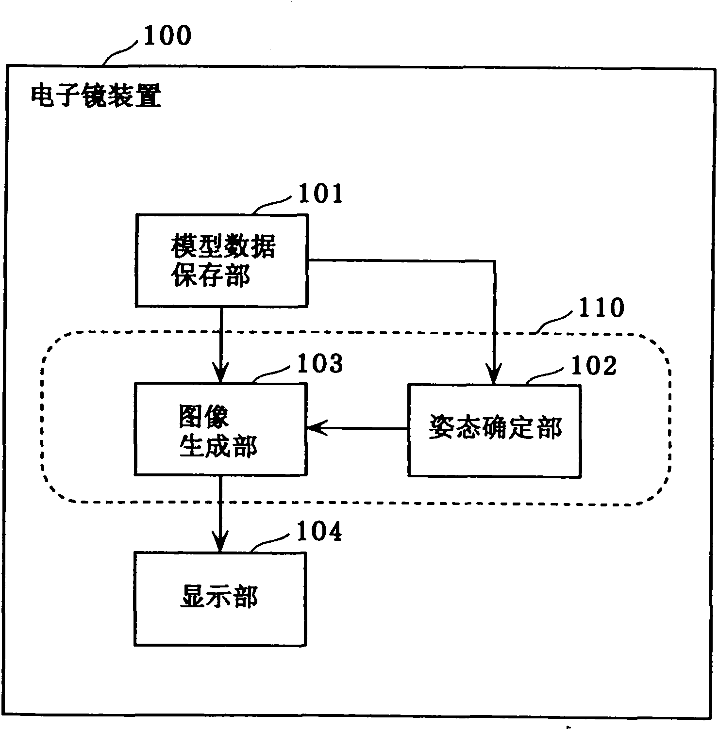
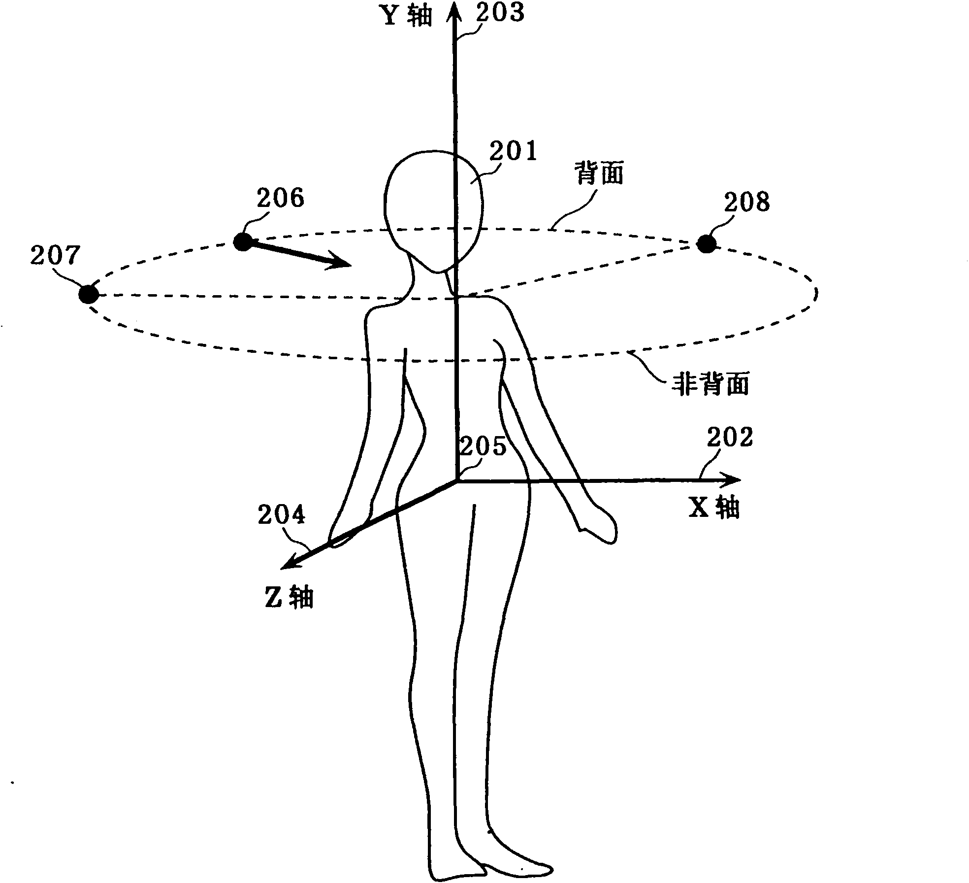
[0047] figure 1 is a block diagram showing the functional configuration of the electronic mirror device according to the first embodiment of the present invention. figure 2 It is an explanatory diagram of the coordinate axes of the model data according to the first embodiment of the present invention. Such as figure 1 As shown, the electronic mirror device 100 includes a model data storage unit 101 , a pose identification unit 102 , an image generation unit 103 , and a display unit 104 .
[0048] For example, the model data storage unit 101 is constituted by a storage medium such as a nonvolatile memory or a volatile memory, and stores user's three-dimensional model data. Specifically, the model data storage unit 101 stores coordinates of 3D model data obtained by measuring the user's body, texture data, light source data, viewpoint, line of sight, and coordinate transformation matrix in the frame as human body model data. Such as figure 2 It is shown that the three-di...
Embodiment 2
[0077] Hereinafter, Embodiment 2 of the present invention will be described with reference to the drawings.
[0078] Figure 6 is a block diagram of the functional structure of the electronic mirror device according to the second embodiment of the present invention. Such as Figure 6 It is shown that the electronic mirror device 400 of the present embodiment does not include the model data storage unit 101 included in the electronic mirror device 100 of the first embodiment. Furthermore, the electronic mirror device 400 of this embodiment includes a camera 401 and a model data generation unit 402 . Also, part of the processing of the posture specifying unit 403 and the image generating unit 404 in this embodiment is different from the posture specifying unit 102 and the image generating unit 103 in the first embodiment. Moreover, in Figure 6 in, for with figure 1 The same symbols are used for the same constituent elements, and explanations are omitted.
[0079] The cam...
Embodiment 3
[0097] Hereinafter, Embodiment 3 of the present invention will be described with reference to the drawings.
[0098] Figure 9 is a block diagram showing the functional structure of the electronic mirror device according to the third embodiment of the present invention. Such as Figure 9 It is shown that the electronic mirror device 600 of the present embodiment includes a memory 601 in addition to the components included in the electronic mirror device 400 of the second embodiment. Also, a part of the processing of the posture specifying unit 602 of the present embodiment is different from that of the posture specifying unit 403 of the second embodiment. Moreover, in Figure 9 in, for with figure 1 or Figure 6 The same symbols are used for the same constituent elements, and explanations are omitted.
[0099] The pose specifying unit 602 refers to the basic data of the human body model registered in the memory 601 in advance, and matches the user's 3D model data genera...
PUM
 Abstract
Description
Claims
Application Information
 - R&D
- Intellectual Property
- Life Sciences
- Materials
- Tech Scout
- Unparalleled Data Quality
- Higher Quality Content
- 60% Fewer Hallucinations
Browse by: Latest US Patents, China's latest patents, Technical Efficacy Thesaurus, Application Domain, Technology Topic, Popular Technical Reports.
© 2025 PatSnap. All rights reserved.Legal|Privacy policy|Modern Slavery Act Transparency Statement|Sitemap|About US| Contact US: help@patsnap.com


