Welding process with jerk compensation

A welding head, field welding technology, applied in the field of flash butt welding field welding system

Active Publication Date: 2010-07-21
CHEMETRON RAILWAY PROD
View PDF3 Cites 2 Cited by
  • Summary
  • Abstract
  • Description
  • Claims
  • Application Information

AI Technical Summary

Problems solved by technology

In addition, although the background section is described for the convenience of readers who may not be skilled in the art, it should be u

Method used


Image

  • Welding process with jerk compensation
  • Welding process with jerk compensation
  • Welding process with jerk compensation

Examples


Embodiment Construction

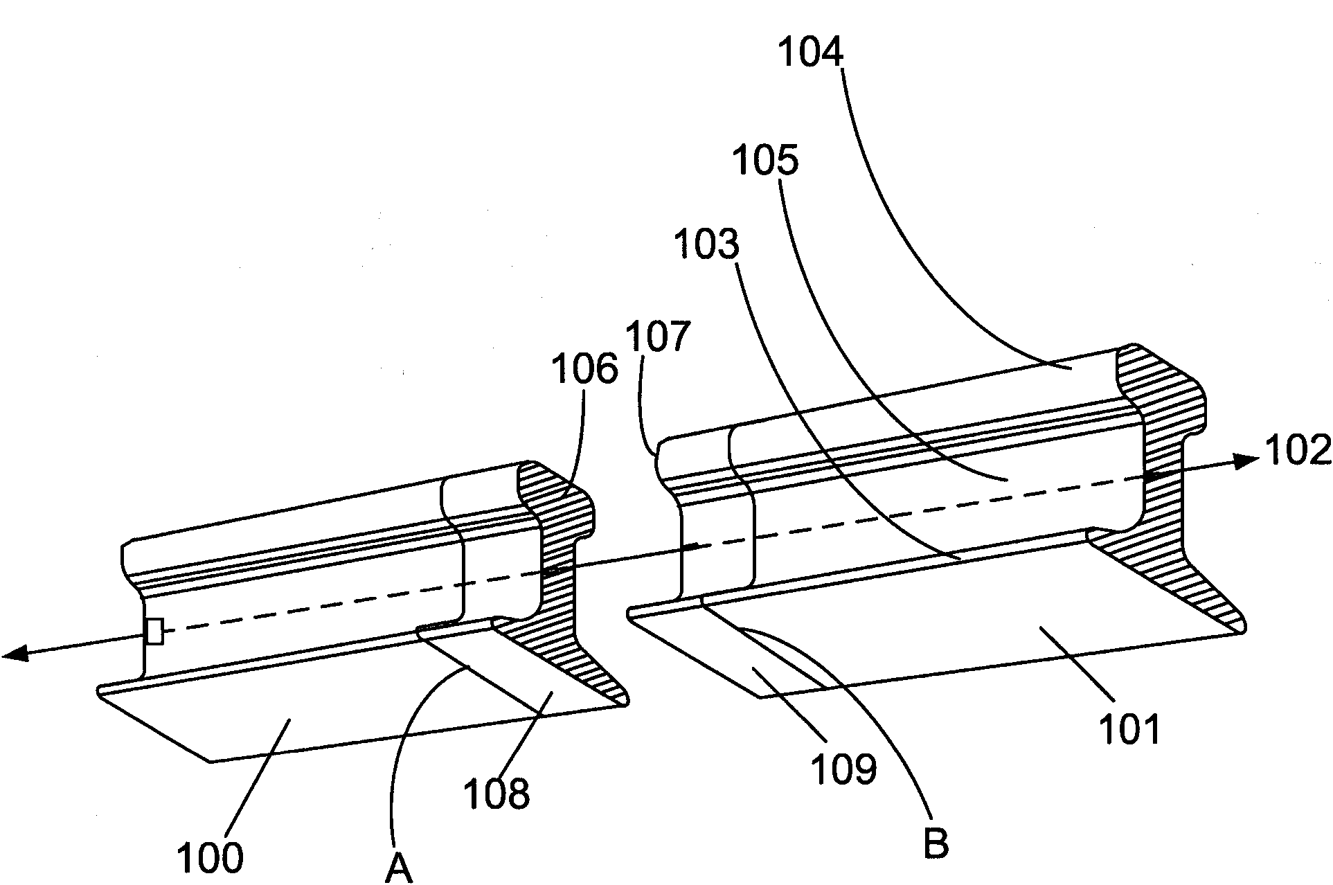
[0016] Railway tracks consist of a pair of side-by-side, continuous steel tracks which may be formed by welding track sections together in a welding process such as flash butt welding. figure 1 is a perspective view of two rail segments in place for flash butt welding according to the invention. In particular, the first track segment 100 and the second track segment 101 are shown aligned with each other along the vertical track axis 102 and slightly spaced between the first track segment 100 and the second track segment 101 . The first track segment 100 and the second track segment 101 each include a track base 103 and a track head 104 . The rail base 103 and the rail head 104 are connected to each other by a rail connection 105 . The track base 103 and the track connection 105 provide the basic strength of the track and also provide the surface area of ​​the junction between track sections, such as between the first track section 100 and the second track section 101 . The t...


PUM


Abstract

An improved welding head for creating an in-track weld between a first rail segment and a second rail segment includes a controller having computer-readable instructions read by the controller. The computer-readable instructions include instructions for compensating for rail jerk during in-track welding. The welding head includes a closing force actuator, such as a hydraulic cylinder, for moving the rail segments toward one another. A pressure transducer is monitored during welding to determine a closing force. An impending jerk of the rail movement is detected if an abnormal closing force change is observed, and in response the flow of hydraulic fluid into or out of the hydraulic cylinder is restricted to prevent or minimize the jerk. In addition, when an impending jerk is detected the weld current may be temporarily increased to burn or prevent the formation of short circuit paths between the rails.

Description

technical field [0001] The present invention relates generally to systems and methods for flash-butt welding of railroad tracks, and more particularly to field welding systems that perform consistent flash-butt welding under adverse temperature and track bed conditions. Background technique [0002] Railroad track welding is commonly used to join two track sections when building or repairing railways. One type of welding is commonly known as flash butt welding. In flash butt welding, the two rail ends to be joined are first heated and then forged together, draining liquid metal and oxides from the welded joint. The forged welded joint is trimmed to remove burrs, ie solidified material that was forced out of the joint during the forged welding process. [0003] Since the welding surface is prepared in some stages of the flash-butt welding process, the speed at which the rail material is manipulated has an important influence on the quality of the weld. For example, if the ...

Claims


Application Information

Patent Timeline
IPC IPC(8): B23K11/36B23K11/04
CPCE01B29/44B23K11/046
Inventor C·R·巴蒂斯蒂G·巴尔恩哈特
Owner CHEMETRON RAILWAY PROD
Why Eureka
Try Eureka